SVPWM仿真与分析论文

1INTRODUCTION
Permanent magnet linear synchronous motor (PMLSM)is a kind of driving equipment for converting electrical energy into linear movement directly without any in-between transferring mechanism [1].Without the need of any mechanical transformation by using for example gears and screws,the linear drive offers high efficiency,high reliability,high performance motion control and low vibration and noise [2].PMLSM s are increasingly used as actuators in many automation control fields,including computer controlled machining tools,X-Y driving devices,robots,semiconductor manufacturing equipment,transport propulsion and levitation,and high-speed injection molding machines [3].The control performance of the PMLSM is sensitive to its load disturbance,friction variation,and end effect.Thus,it is important to adopt a proper control strategy to achieve satisfied servo performance.
Digital control techniques of AC motors,such as the space vector pulse width modulation (SVPWM),have been developed with wide range industrial applications.The SVPWM was brought forward from 1980’s,specifically used for the frequency varying and speed regulation of AC motors.It controls the motor based on the switching of space voltage vectors,by which an approximate circular rotary magnetic field is https://www.docsj.com/doc/8a3747910.html,paring with the sine pulse width modulation (SPWM),the main SVPWM advantage is that it has e.g.a 15%higher utilization ratio of voltage [4].In addition,SVPWM can improve the quality of the stator currents and reduce the harmonic wave generation.
Consequently,SVPWM is adopted as the servo control strategy for the PMLSM in this paper and its simulation model is built in Matlab/Simulink.
Two substantial simulation results are presented in this paper.One is under open-loop control system based
This work is supported by the Chinese High-Tech Development Program (863),Project No.2007AA03Z208.
SVPWM,and the control effectiveness of it is analyzed.The other is field-oriented vector control (VC)based close-loop control system,and the position-tracking control algorithm is proposed and simulated.Analytical results are obtained and
presented with comparison.
2MODEL OF PMLSM
2.1Coordinate transformations
PMLSM is a nonlinear and strong coupling system.Coordinate transformation can simplify the mathematic model of PMLSM.The typical mathematical model of PMLSM is described in two-axis d-q synchronous rotating reference frame.In d-q frame,if the current in the direction of d-axis can be set zero,then controlling the thrust force of PMLSM is the only need to control the current in the direction of q-axis.So the coordinate transformation is very important to decouple the nonlinear of PMLSM.The following shows transformation formulas among the stationary a-b-c frame,the stationary α-βframe and the synchronously rotating d-q frame,where V represents a space vector i.e.current,voltage or magnet flux linkage.(1)Clark transformation:stationary a-b-c frame to
stationary α-β
frame
111220
22a b
c V
V V V V αβ??=????
?????
????????????(1)(2)Clark -1transformation:stationary α-βframe to
stationary a-b-c frame
Simulation and Analysis of a PMLSM Control System Based on SVPWM
JIN Jianxun 1,ZHAO Huibin 1,XIN Ying 2, SUN Yuwei 2
1.Center of Applied Superconductivity and Electrical Engineering,
University of Electronic Science and Technology of China,Chengdu 61173,P.R.China
E-mail: jxjin@https://www.docsj.com/doc/8a3747910.html,
2.Innopower Superconductor Cable Co.,Ltd,Beijing ,P.R.China
E-mail:yingxin@https://www.docsj.com/doc/8a3747910.html,
Abstract:This paper aims to develop a permanent magnet synchronous motor (PMLSM)control system based on space vector pulse width modulation (SVPWM)and analyzes its control effectiveness.Mathematical simulation models of PMLSM and SVPWM are firstly presented and established in Matlab/Simulink.An open-loop simulating control system and a field-oriented vector control (VC)based close-loop system are then built,and their control effectiveness is analyzed.To overcome the shortages of great overshooting and poor dynamic response of the traditional VC and improve the precision of position,a position-tracking control strategy is proposed and simulated.Analytica l results indicate that the proposed strategy can improve the stability and precision of the PMLSM control system.Key Words:PMLSM,SVPWM,Matlab/Simulink,Vector control,Simulation
Proceedings of the 29th Chinese Control Conference July 29-31, 2010, Beijing, China
10
1
22
1
22
a
b
c
V
V
V
V
V
α
β
?
=
??
??
?
???
??
???
??
????
??
???
??
(2)
(3)Park transformation:stationaryα-βframe to
synchronously rotating d-q frame
cos sin
sin cos
d
q
V V
V V
α
β
θθ
θθ
=
?
????
??
????
??
????
??
(3)
(4)Park-1transformation:synchronously rotating d-q
frame to stationaryα-βframe
cos sin
sin cos
d
q
V
V
V
V
α
β
θθ
θθ
?
=
??
????
??
????
??
????
(4)
2.2Mathematical model of PMLSM
There are a few hypotheses in the process of mathematics
model foundation.The iron core saturation is neglected,and
the losses of eddy currents,hysteresis and end effect aren’t
taken into account.The typical mathematical model of a
PMLSM is commonly described in two-axis d-q
synchronous rotating reference frame[5],as follows.
Stator voltage balance equation is given by
d
d d d q q
di
u Ri L vL i
dt
π
τ
=+?(5)
()
q
q q q d d f
di
u Ri L L i v
dt
π
?
τ
=+++(6)
The electromagnetic thrust force is given by
3
[()]
2
em f d q d q
F L L i i
π
ψ
τ
=+?(7)
If i d=0,electromagnetic thrust force would be expressed as
3
2
em f q p q
F i K i
π
τ
==(8)
Therefore the thrust force of PMLSM can be controlled just
through the controlling of i q which is very like controlling a
DC motor.
Considering the mechanical load,the dynamic position
movement mechanical balance equation of PMLSM is given
by
em d
dv
F F Bv M
dt
=++(9)
whereψf,F d,B, M,v, R,τare the flux linkage of permanent
magnet,external force,viscous friction coefficient,mass of
moving part,translator velocity,phase winding resistance,
pole pitch.
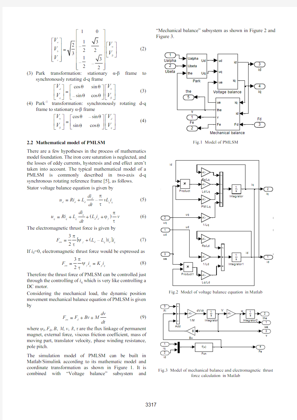
The simulation model of PMLSM can be built in
Matlab/Simulink according to its mathematic model and
coordinate transformation as shown in Figure 1.It is
combined with“Voltage balance”subsystem and
“Mechanical balance”subsystem as shown in Figure2and
Figure3.
Fig.1Model of PMLSM
Fig.2Model of voltage balance equation in Matlab
Fig.3Model of mechanical balance and electromagnetic thrust
force calculation in Matlab
3MODEL OF SVPWM
3.1Principle of SVPWM
The reference stator voltage space vector for PMLSM U ref can be defined as
2
4
23
3
2()3
j j j ft
ref a b c ref U U U e
U e
U e
πππ=
++=(10)
Fig.4Space vector diagram
The three-phase voltage source inverter has six electronic switches e.g.IGBTs (Insulated gate bipolar transistors)and eight working states,which topology structure has eight voltage vectors shown in Figure 4.According to compound voltage vector and voltage s econd balance principle,stator voltage vector U ref in any switch period can be calculated by two basic adjacent voltages vectors corresponding to two switch modes of the IGBT as shown in Figure 5
1
7
017sk
sk ref sk sk T T T T U U U U U T T T T
++=
+
+
+
(11)
where T is switch period,T sk and T sk+1are operating time of U sk and U sk+1respectively,T 0and T 7are operating time of U 0and U 7.
Fig.5Voltage space vectors linear combination
3.2Simulating model of SVPWM built in Matlab
Simulink According reference [6],the flow chart of building the model of SVPWM is shown in Figure 6.The simulation model of SVPWM in Matlab/Simulink is shown in Figure 7.It combined with four subsystems:“section calculate”subsystem,“operating time”subsystem,“PWM generate”subsystem and “inverter”subsystem.The output of inverter is given by formula (12).S a ,S b ,and S c represent the states of six IGBT switches in inverter
211112131
1
2a b d c a b c U S U S U S V ??=????????????????
????????????
(12)
Fig.6Flow chart of building the model of SVPWM
Section calculate
Fig.7Simulation model of SVPWM
4
SIMULATION AND ANALYSIS OF
OPEN-LOOP CONTROL
Fig.8:Simulating model of open-loop control system
The simulating model of open-loop control system of PMLSM is shown in Figure 8.Parameters of the designed PMLSM are:M =10kg,R =10Ω,B =0.1,τ=10mm,L d =L q =10mH,Ψf =0.5Wb,F d =50N.Three-phase voltage signal with amplitude of 50V and frequency of 10Hz is added to Clark transformation model.The PWM period or called switch period T s of SVPWM is 0.001s,and the DC bus voltage V dc of inverter is 500V.
Fig.9Simulation result of PMLSM
U sk
U sk+1
U ref
U sk T sk /T
U sk T sk+1/T
As shown in Figure 9,the stabilized velocity 0.2m/s is same as the result calculated by formula (13).The displacement curve is the integration of velocity
2v f τ=(13)where f is the PMLSM frequency of phase voltage.
But the electromagnet thrust force curve in Figure 9is not a constant.The average of electromagnet thrust force is 50N,and some time F >0,some time F <0.When F >0,work of electromagnet thrust force is positive,when F <0,work is negative.The mechanical efficiency can be derived as follows.
Assume the mass of moving part is m ,electromagnet thrust force is F ,and external force is f
()()()11222233334
00&&00&&0F f t t t F F f F t t t F f F t t t ?><<=?<><
???(14)
The velocity of rotor is as
2
3
4
1
2
3
3
1
2
t t t t t t
F F F v dt dt C
m m m
=
++=∫
∫
∫
(15)
Power of electromagnet thrust force is as
1122233
34))0(0
(0()W t t t W W t t t W t t t ><<=><<<<
???(16)
2
12312
f
W W W mv W ++=+(17)
where W f is the power to overcome the friction.
Whether the work of electromagnet thrust force is positive or negative,the energy of motor will be consumed equally.The total energy consumed can be expressed as
123'||||||
W W W W =++(18)
Naturally the mechanical efficiency ηis derived from (17)and (18)
123123||||||W W W W W W η++=
++(19)
The remaining energy is converted to heat Q
'
(1)
Q W η=?(20)
So it is necessary to design a better control system to reduce the heat generating and increase η.The key to resolve the problem includes the stability of electromagnet thrust force and quick respond to velocity.So the close-loop control system need s to be established.
5
DESIGN AND ANALYSIS OF CLOSE-LOOP CONTROL SYSTEM BASED ON VC
The field-oriented vector control (VC)was firstly presented in 1971for induction motors and later for permanent magnet synchronous motors (PMSM)[7].
According to formula (7)and (8),electromagnet thrust force is decided only by i q if i d =0.The velocity can be adjusted by thrust force according to formula (9),and the displacement is the integration of velocity,so the position can be controlled as well.That is the three-close-loop VC control strategy which is shown in Figure
11.
Fig.10Position step respond
Currently,the proportional-integral-derivative (PID)algorithm is the most common control algorithm used in industry.This paper use PID algorithm and position trajectory algorithm to realize accurate position control.The parameters of PIDs are listed in Table 1.If there is no trajectory plan before position loop,the position control can’t achieve a good result,greater overshoot and error will be generated as the Figure 10shown.
The trajectory plan module is to realize trapezoid curve movement.Assume P s ,P f and X p is the setting position,feedback position and command position correspondingly;a cc ,and A cc is the setting acceleration and commanding acceleration.All variable are positive by default.The algorithm is as follows , a nd the simulated result is shown in Figure 12.When 13
f s
P P ≤then A cc = a cc ;when
1233f s
P P <≤then
A cc =0;when
213f s
P P <≤then A cc =-a cc ;s cc P A dt =∫∫and P s X p
Tab.1:Parameters of PID controllers
T c :Time constant for derivatives;T s :Sample time
Parameters K p K i K d T c (s)T s (s)Position loop PID 300100.10.5e-21e-4Speed loop PID 20020.10.5e-21e-5I q loop PID 2000.50.050.5e-31e-5I d loop PID
150
1
0.03
0.5e-3
1e-5
Fig.11:Three-closed-loop control system with trajectory plan
Fig.12:Simulation result of trajectory plan position control
Comparing with Figure 10and Figure 12,the trajectory plan position control can control the velocity curve and decrease the displacement error,and the thrust force has little fluctuation which is often positive.Therefore trajectory control can improve the stabilization of the system and increase the mechanical efficiency according to the formula (19).
6CONCLUSION
Simulation models of PMLSM and SVPWM are established in Matlab/Simulink.The analytical and experimental results indicate that the model is accurate and practicable.The open-loop control system of PMLSM is presented and established,and the simulation result indicates that the open-loop control system can’t reach the aim of high accurate position control and the mechanical efficiency is lower.Consequently the close-loop control system is introduced.Field-oriented vector control system can improve the position precision,but its overshooting
phenomena can’t be eliminated and the velocity of moving part is volatile.So it need to add a trajectory plan module before position loop to set the displacement track which make the velocity curve trapezoid as shown by the velocity curve in Figure 12.The experiment results indicate that the proposed position-tracking control strategy can decrease the overshooting effect and improve the precision of position.
REFERENCES
[1]H.B.Zhao,J. X.Jin,and J.Cheng. Virtual instrument based
fuzzy control system for PMLSM drive.Chengdu:Proceeding of IEEE on Applied Superconductivity and Electromagnetic Devices,2009:299-303.
[2]Y.G.Guo,J.X.Jin,J.G.Zhu,and H.Y.Lu.Design and
analysis of a prototype linear motor driving system for HTS maglev transportation,IEEE Trans.App.Super.,2007,17(2),2087-2090.
[3]Y.S.Kung,M.H.Tsai,C.S.Chen.FPGA-based servo
control IC for PMLSM drives with adaptive fuzzy control.Korea:SICE-ICASE International joint conference 2006,2006:1-6.
[4]Z.G.Wang,J.X.Jin,Y.G.Guo,and J.G.Zhu.SVPWM
techniques and applications in HTS PMSM machines control,Journal of Electronic Science and Technology of China,2008,6(2),191-197.
[5]L. H.Zheng,and J. X.Jin.Investigation of HTS bulk magnet
linear synchronous motors.Chengdu:Proceeding of IEEE on Applied Superconductivity and Electromagnetic Devices,2009:17-21.
[6]J.X.Jin,and L.H.Zheng.A permanent magnet linear
synchronous motor control system based on space vector pulse width modulation,CAAI Transactions on Intelligent Systems,2009,4(3),251-257.
[7]L.Zhong,M.F.Rarman,W.Y.Hu,et al.Analysis of direct
torque control in permanent magnet synchronous motor drives,IEEE Transactions on Power Electronics,1997,12(3),528-536.
三点式正弦波振荡器(高频电子线路实验报告)
三点式正弦波振荡器 一、实验目的 1、 掌握三点式正弦波振荡器电路的基本原理,起振条件,振荡电路设计及电路参数计 算。 2、 通过实验掌握晶体管静态工作点、反馈系数大小、负载变化对起振和振荡幅度的影 响。 3、 研究外界条件(温度、电源电压、负载变化)对振荡器频率稳定度的影响。 二、实验内容 1、 熟悉振荡器模块各元件及其作用。 2、 进行LC 振荡器波段工作研究。 3、 研究LC 振荡器中静态工作点、反馈系数以及负载对振荡器的影响。 4、 测试LC 振荡器的频率稳定度。 三、实验仪器 1、模块 3 1块 2、频率计模块 1块 3、双踪示波器 1台 4、万用表 1块 四、基本原理 实验原理图见下页图1。 将开关S 1的1拨下2拨上, S2全部断开,由晶体管N1和C 3、C 10、C 11、C4、CC1、L1构成电容反馈三点式振荡器的改进型振荡器——西勒振荡器,电容CCI 可用来改变振荡频率。 ) 14(121 0CC C L f += π 振荡器的频率约为4.5MHz (计算振荡频率可调范围) 振荡电路反馈系数 F= 32.0470 220220 3311≈+=+C C C 振荡器输出通过耦合电容C 5(10P )加到由N2组成的射极跟随器的输入端,因C 5容量很小,再加上射随器的输入阻抗很高,可以减小负载对振荡器的影响。射随器输出信号经
N3调谐放大,再经变压器耦合从P1输出。 图1 正弦波振荡器(4.5MHz ) 五、实验步骤 1、根据图1在实验板上找到振荡器各零件的位置并熟悉各元件的作用。 2、研究振荡器静态工作点对振荡幅度的影响。 (1)将开关S1拨为“01”,S2拨为“00”,构成LC 振荡器。 (2)改变上偏置电位器W1,记下N1发射极电流I eo (=11 R V e ,R11=1K)(将万用表红 表笔接TP2,黑表笔接地测量V e ),并用示波测量对应点TP4的振荡幅度V P-P ,填于表1中,分析输出振荡电压和振荡管静态工作点的关系,测量值记于表2中。 3、测量振荡器输出频率范围 将频率计接于P1处,改变CC1,用示波器从TP8观察波形及输出频率的变化情况,记录最高频率和最低频率填于表3中。 六、实验结果 1、步骤2振荡幅度V P-P 见表1.
武汉理工大学数学建模与仿真论文
武汉理工大学2014年数学建模课程论文题目:金属板的切割问题 姓名:李冬波 学院:自动化学院 专业:自动化 学号:012121136329 选课老师:何朗 2014年6月22日
摘要 金属板的切割问题要求对金属板的切割方式进行构思,希望通过数学可以达到效率较高、成本较低的可能性。应该先通过穷举的方法找到所有可能性,在所有可能性中保留最优的可能性。所谓最优即效率较高、成本较低的可能。 在确立了6种切割模式的基础上,再建立非线性规划的数学模型,以模式为基点,将题中订单需求转化为求解金属原料此目标函数的约束条件。在通过LINGO软件的数学规划模型求解功能求解出目标函数值,并通过检验证明,该模型求解出的最少原料使用量与具体切割模式是完全满足题目要求的。 关键词:切割模式、非线性规划、 LINGO
目录 一、问题重述 ------------------------------4 二、问题假设 ------------------------------4 三、模型建立----------------------------------------------5 符号说明------------------------------------------------5 建立模型------------------------------------------------5 四、模型求解----------------------------------------------6 五、求解结果---------------------------------------------7 六、结果检验分析---------------------------------------7 七丶结论-----------------------------------------------8 八、参考文献---------------------------------------------8
高频电子线路实验合集
实验名称:高频小信号放大器 系别:计算机系年级:2015 专业:电子信息工程 班级:学号: 姓名: 成绩: 任课教师: 2015年月日
实验一高频小信号放大器 一、实验目的 1、掌握小信号调谐放大器的基本工作原理; 2、掌握谐振放大器电压增益、通频带、选择性的定义、测试及计算; 3、了解高频小信号放大器动态围的测试方法; 二、主要仪器设备 在计算机上用仿真软件模拟现实的效果, 通过采用仿真技术,虚拟构建一个直观、可视化的2D、3D 实验环境,从而达到对实验现象和实验结果的虚拟仿真以及对现实实验的操作,为处于不同时间、空间的实验者提供虚拟仿真的实验环境,使学习者仿佛置身其中,对仪器、设备、容等实验项目进行互动操作和练习。 二、实验原理 二、实验步骤
1、绘制电路 利用Mulisim软件绘制如图1-1所示的单调谐高频小信号实验电路。 图1-1 单调谐高频小信号实验电路 2、用示波器观察输入和输出波形; 输入波形:
输出波形: 3、利用软件中的波特测试仪观察通频带。
5.实验数据处理与分析 根据电路中选频网络参数值,计算该电路的谐振频率ωp ; s rad CL w p /936.210 58010 2001 16 12 =???= = -- 通过仿真,观察示波器中的输入输出波形,计算电压增益A v0。 ,708.356uV V I = ,544.1mV V O = === 357 .0544 .10I O v V V A 4.325 4、改变信号源的频率(信号源幅值不变),通过示波器或着万用表测量输出电压的有效值,计算出输出电压的振幅值,完成下列表,并汇出f~A v 相应的图,根据图粗略计算出通频带。 f 0(KHz ) 65 75 165 265 365 465 1065 1665 226 5 2865 3465 4065 U 0 (mv) 0.97 7 1.064 1.39 2 1.48 3 1.528 1.54 8 1.45 7 1.28 2 1.09 5 0479 0.84 0 0.74 7 A V 2.73 6 2.974 3.89 9 4.154 4.280 4.33 6 4.08 1 3.59 1 3.06 7 1.34 1 2.35 2 2.09 2 (5)在电路的输入端加入谐振频率的2、4、6次谐波,通过示波器观察图形,体会该电路的选频作用。
高频电子线路实训论文要点
编号: 高频电路设计与制作 实训论文说明书 题目:调频接收机 学院: 专业: 学生姓名: 学号: 指导教师: 2014年1 月9 日
摘要 收音机从它的诞生至今,不仅方便了媒体信息的传播,也推进了现代电子技术和更先进的电信设备的发展。目前调频式或调幅式收音机,一般都采用超外差式,它具有灵敏度高、工作稳定、选择性好及失真度小等优点。随着科学技术的发展,调频收音机的应用十分广泛,尤其消费类占有相当的市场。从分立元件组成的收音机到集成电路组成的收音机,调频收音机技术以达到十分成熟的地步。从普通的调幅收音机到高级调频收音机,调频收音机以较高的技术含量和较高的音质得到了广泛的欢迎。 在本次设计中,主要是利用集成电路CXA1691BM搭建成为接收机电路。该系统要求能对不同波形的话音信号进行调制、发送、接收和解调。CXA1691BM是一个单芯片FM/AM 收音IC专用无线收录机,由索尼公司生产。使用它来制作收音机可以实现通信的可靠性、通信的距离、设备的微型化、省电和轻巧等。CXA1691BM是一块适用于单声道便携式或手掌式超小型调频收音机的专业电路。应用时外围元件少,成本低廉,电路简单,调试方便,性能稳定等等优点,可以优先选择该电路设计制作收音机。 关键词:CXA1691BM;调频;接收机
Abstract The radio from its birth until now, went to the lavatory not only media dissemination of information, but also promote the modern electronic technology and more advanced telecommunications equipment development. Currently FM type or amplitude type radio, typically use the specialized super heterodyne type; it has a high sensitivity, stable and good selectivity and the distortion degree of small advantages. With the development of science and technology, the FM radio is widely used, especially the consumer a considerable market. Radio from discrete components to integrated circuits consisting of radio, FM radio technology to reach a mature stage. From ordinary AM radio to advanced FM radio, FM radio with high technological content and high sound quality has been widely welcomed. In the design, mainly to take advantage of the integrated circuit CXA1691BM structures become the receiver circuit. The system required for modulating the voice signal of the different waveforms, the transmission, reception and demodulation. CXA1691BM is a single-chip FM / AM radio IC dedicated wireless radio cassette recorders manufactured by Sony. Use it to produce the radio can be achieved the reliability of communication, the communication distance, the miniaturization of the device, saving and lightweight, etc... CXA1691BM a mono portable or palm small FM radio professional circuit. Fewer external components in the application, and low cost, simple circuit, commissioning, stable performance advantages, Radio Select the circuit design. Keywords: CXA1691BM;frequency modulation;Receiver
二极管包络检波实验,实验二,高频电子线路实验报告,南京理工大学紫金学院
高频实验报告 实验名称:二极管包络检波实验 姓名: 学号: 班级:通信 时间:2013.12 南京理工大学紫金学院电光系
一、 实验目的 1.加深对二极管大信号包络检波工作原理的理解。 2.掌握用二极管大信号包络检波器实现普通调幅波(AM )解调的方法。了解滤波电容数值对AM 波解调影响。 3.了解电路参数对普通调幅波(AM )解调影响。 图4-1是二极管大信号包络检波电路,图4-2表明了大信号检波的工作原理。输入信号)(t u i 为正并超过C 和1R 上的)(0t u 时,二极管导通,信号通过二极管向C 充电,此时)(0t u 随充电电压上升而升高。当)(t u i 下降且小于)(0t u 时,二极管反向截止,此时停止向C 充电并通过L R 放电,)(0t u 随放电而下降。充电时,二极管的正向电阻D r 较小,充电较快,)(0t u 以接近)(t u i 上升的速率升高。放电时,因电阻L R 比D r 大的多(通常Ω=k R L 10~5),放电慢,故)(0t u 的波动小,并保证基本上接近于)(t u i 的幅值。如果)(t u i 是高频等幅波,则)(0t u 是大小为0U 的直流电压(忽略了少量的高频成分),这正是带有滤波电容的整流电路。当输入信号)(t u i 的幅度增大或减少时,检波器输出电压)(0t u 也将随之近似成比例地升高或降低。当输入信号为调幅波时,检波器输出电压)(0t u 就随着调幅波的包络线
而变化,从而获得调制信号,完成检波作用,由于输出电压)(0t u 的大小与输入电压的峰值接近相等,故把这种检波器称为峰值包络检波器。 2.二极管大信号包络检波效率 检波效率又称电压传输系数,用d η表示。它是检波器的主要性能指标之一,用来描述检波器将高频调幅波转换为低频电压的能力。d η定义为: cm a m cm a m d U m U U m U ΩΩ= = )()(调幅波包线变化的幅度检出的音频电压幅度η 当检波器输入为高频等幅波时,输出平均电压0U ,则d η定义为 cm cm d U U U U 00)()(== 检波电压的幅值整出的直流电压η 这两个定义是一致的,对于同一个检波器,它们的值是相同的。由于检波原理分析可知,二极管包络检波器当C R L 很大而D r 很小时,输出低频电压振幅只略小于调幅波包络振幅,故d η略小于1,实际上d η在80%左右。并且R 足够大时, d η为常数,即检波器输出电压的平均值与输入高频电压的振幅成线性关系,所 以又把二极管峰值包络检波称为线性检波。检波效率与电路参数L R 、C 、0r 以及信号大小有关。它很难用一个简单关系式表达,所以简单的理论计算还不如根据经验估算可靠。如要更精确一些,则可查图表并配以必要实测数据得到。 3.二极管大信号包络检波器输入电阻 输入电阻是检波器的另一个重要的性能指标。对于高频输入信号源来说,检波器相当于一个负载,此负载就是检波器的等效输入电阻in R 。 d L in R R η2~- 上式说明,大信号输入电阻in R 等于负载电阻的一半再除以d η。例如 Ω=k R L 1.5,当d η=0.8,时,则Ω=?= k R in 2.38 .021 .5。 由此数据可知,一般大信号检波比小信号检波输入电阻大。 3.二极管大信号包络检波器检波失真
毕业论文----汽车防抱死制动系统的建模与仿真(含开题报告 中英文翻译)
分类号编号 毕业论文 题目汽车防抱制动系统的建模与仿真 ——模糊控制在ABS中的应用 学院机械学院 专业机械设计制造及其自动化
毕业设计任务书 设计题目:汽车防抱制动系统的建模与仿真 专业:机械设计制造及其自动化 班级学号: 姓名: 院、系:机械学院 2010年2 月26 日
一、毕业设计的目的 毕业设计是本科教育中培养学生的重要的实践性教学环节,也是最后一个教学环节。其目的: 1.培养学生综合运用基础理论知识、专业知识和技能,解决工程实际问题的能力; 2.培养学生运用机械设计手册、图册、国家标准规范和规程的能力; 3.培养学生学会机械设计的思想、方法和步骤,掌握计算方法、掌握计算机绘图及 编写工程设计文件等基本技能; 4.提高学生分析问题、解决问题和独立工作的能力。 二、主要设计内容 1.专业外文资料翻译; 2.毕业实习,实习报告; 3.开题报告; 4.汽车防抱制动系统的建模与仿真。 三、重点研究问题 1.汽车防抱制动系统的车辆仿真模型的建立; 2.采用的控制方法模型的建立; 四、主要技术指标和主要设计参数 1.收集资料确定一个自己的设计参数,在查阅资料后确定下来。 2.控制方法根据所查找文献自己确定。 五、设计成果要求 1.开题报告1份(要求3 000字左右、查阅文献10篇以上、文献综述引用5篇以上, 样表从教务处表格下载中下载); 2.实习报告1份; 3.专业外文资料翻译1篇(不少于2 000汉字); 4.毕业设计(论文)1份(设计说明书应在10000字以上,论文应在6000字以上, 包括封面、任务书、开题报告、中英文摘要、目录、正文、参考文献、附录); 5.设计图纸一套(不少于A0图2张); 6.所有内容电子文档一套; 7.毕业论文成果材料清单一份。
毕业论文:浅谈虚拟现实技术
论文虚拟现实技术
浅谈虚拟现实技术 摘要虚拟现实(Virtual Reality,VR)技术是近年来新兴的借助计算机及最新传感器技术创造的一种崭新的人机交互手段,其核心是建模与仿真。概括介绍了虚拟现实技术的概念、特征及应用领域,涉及的关键技术,最新研究进展,应用与前景展望。 关键词虚拟现实技术,研究现状,相关应用,信息安全 一.虚拟现实的概念、特征及应用领域 虚拟现实是一种由计算机和电子技术创造的新世界,是一个看似真实的模拟环境,通过多种传感设备,用户可根据自身的感觉,使用人的自然技能对虚拟世界中的物体进行考察和操作,参与其中的事件,同时提供视、听、触等直观而自然的实时感知,并使参与者“沉浸”于模拟环境中。虚拟现实(Virtual Reality,VR)技术是指借助计算机及最新传感器技术创造的一种崭新的人机交互手段,其核心是建模与仿真。 虚拟现实技术主要包括模拟环境、感知、自然技能和传感设各等方面。模拟环境是由计算机生成的、实时动态的三维立体逼真图像。感知是指理想的VR应该具有一切人所具有的感知。除计算机图形技术所生成的视觉感知外,还有听觉、触觉、力觉、运动等感知,甚至还包括嗅觉和味觉等,也称为多感知。自然技能是指人的头部转动,眼睛、手势、或其他人体行为动作,由计算机来处理与参与者的动作相适应的数据,并对用户的输入作出实时响应,并分别反馈到用户的五官。传感设备是指三维交互设备。常用的有立体头盔、数据于套、三维鼠标、数据衣等穿戴于用户身上的装置和设置于现实环境中的传感装置,如摄像机、地板压力传感器等。 (虚拟现实技术穿戴的装备)
GrigoreBurdea和Philippe Coiffet在著作“Virtual Reality Technology”一书中指出,虚拟现实具有三个最突出的特征,即人们称道的“3I”特性:交互性(interactivity) 、沉浸感(Illusion of Immersion) 和构想性(imagination)。交互性主要是指参与者通过使用专门输入和输出设备,用人类的自然技能实现对模拟环境的考察与操作的程度。沉浸感是虚拟现实最主要的技术特征,它是指参与者在纯自然的状态下,借助交互设备和自身的感知觉系统,对虚拟环境的投入程度。构想性是指借助虚拟现实技术,使抽象概念具像化的程度。另外还有多感知性(Multi-Sensory)。所谓多感知是指除了一般计算机技术所具有的视觉感知之外,还有听觉感知、力觉感知、触觉感知、运动感知,甚至包括味觉感知、嗅觉感知等。理想的虚拟现实技术应该具有一切人所具有的感知功能,由于相关技术,特别是传感技术的限制,目前虚拟现实技术所具有的感知功能仅限于视觉、听觉、力觉、触觉、运动等几种。 所以,“3I+M”就是虚拟现实系统的基本特征。 自1968年Ivan Sutherland发表一篇名为“The Ultimate Display”的论文至今,虚拟现实技术已经伴随着计算机技术的进步得到长足的发展。如今,众多的设备可被用于虚拟现实,包括头戴式显示器、数据手套、动作捕捉系统等[1]。虚拟现实技术已经在诸如建筑设计、军事仿真、虚拟制造、游戏娱乐、医学等领域得到广泛的应用。在教育、心理学、环保、文化艺术领域,虚拟现实技术也得到越来越多的关注[2]。 二.虚拟现实涉及的关键技术[3] 虚拟现实的关键技术主要包括:动态环境建模技术,实时三维图形生成技术,立体显示和传感器技术,应用系统开发工具,系统集成技术,实时三维计算机图形技术,广角立体显示技术,对观察者头、眼和手的跟踪技术,触觉、力觉反馈技术,立体声、语音输入输出技术。 动态环境建模技术:虚拟环境的建立是VR系统的核心内容,目的就是获取实际环境的三维数据,并根据应用的需要建立相应的虚拟环境模型。 实时三维图形生成技术:三维图形的生成技术已经较为成熟,那么关键就是“实时”生成。为了达到实时的目的,至少保证图形的刷新频率不低于15帧/秒,最好高于30帧/秒。
高频电子线路-am调制与解调电路设计_本科论文
提供全套毕业论文,各专业都有 海南大学课程论文 课程名称:高频电子线路课程设计 题目名称:AM调制与解调电路设计 学院:信息科学技术学院 专业班级:12级通信工程B班 姓名: 学号:20121613310103 指导老师:
目录 一、题目分析 (3) 1.前言 (3) 2.基本理论 (3) 二、电路设计 (4) 1.仿真分析 (4) 2.设计要求 (6) 3.设计内容 (6) (1)电路设计 (6) (2)调幅电路 (7) (3)解调电路 (9) 三、心得体会 (10) 四、问题分析 (12) 五、参考文献 (13)
基于Multisim的调幅电路的仿真 1.前言 信号调制可以将信号的频谱搬移到任意位置,从而有利于信号的传送,并且是频谱资源得到充分利用。调制作用的实质就是使相同频率范围的信号分别依托于不同频率的载波上,接收机就可以分离出所需的频率信号,不致相互干扰。而要还原出被调制的信号就需要解调电路。调制与解调在高频通信领域有着广泛的应用,同时也是信号处理应用的重要问题之一,系统的仿真和分析是设计过程中的重要步骤和必要的保证。论文利用Multisim提供的示波器模块,分别对信号的调幅和解调进行了波形分析。 AM调制优点在于系统结构简单,价格低廉,所以至今仍广泛应用于无线但广播。 论文主要是综述现代通信系统中AM 调制解调的基本技术,并分别在时域讨论振幅调制与解调的基本原理, 以及介绍分析有关电路组成。此课程设计的目的在于进一步巩固高频、通信原理等相关专业课上所学关于频率调制与解调等相关内容。同时培养分析问题、解决问题的综合能力。 2.基本理论 由于从消息转换过来的调制信号具有频率较低的频谱分量,这种信号在许多信道中不宜传输。因此,在通信系统的发送端通常需要有调制过程,同时在接受端则需要有解调过程从而还原出调制信号。 所谓调制就是利用原始信号控制高频载波信号的某一参数,使这
汽车建模与仿真论文
基于Simulink的汽车ABS建模与仿真分析 摘要:汽车防抱死系统(ABS)是一种在制动时能够自动调节车轮制动力,防止车轮抱死以取得最佳制动效果的制动系统。该系统能够有效的缩短制动距离、提高制动时的方向稳定性,对汽车的行驶安全具有重要的意义。本文介绍了ABS的工作原 理,分析了ABS的系统模型,基于Matlab/Simulink环境, 建立了一个车辆制动防抱系统仿真模型,并对仿真结果进行了分析。关键词:制动;防抱死系统;建模仿真 Abstract:Anti-lock braking system(ABS) is a kind of device,which can regulate the wheel’s braking force automatically,prevent the wheels from locking and acquire the best effect during braking.This device is significant to steering safety. This paper introduced the principle of operation of ABS,analysed the system model of ABS,established a simulation model of vehicle ABS on Matlab/Simulink and had an analysis about the results. Key words:braking;ABS;modeling and simulation 前言 汽车是当今世界最主要的交通工具之一,而汽车运输的安全性、经济性和舒适性是人们所关注的焦点。汽车的制动性能是表征汽车行驶安全性的一个主要指标,重大的交通事故往往与制动距离过长和紧急制动时发生侧滑等情况有关,随着汽车拥有量和汽车平均行驶速度的不断提高,交通事故给人们带来的危害日益严重,研究和改善汽车的制动性能成为汽车设计与开发部门的重要课题。在汽车制动过程中,ABS会自动调节车轮轮缸的制动压力,把车轮滑移率控制在一定范围内,防止车轮产生抱死,达到提高汽车制动过程中的操纵稳定性、并缩短制动距离的目的。 开发汽车的ABS需要通过大量的实车试验来确定汽车ABS系统的结构与工作参数,也可以通过对汽车ABS系统的仿真研究初步确定ABS系统的参数,再确定实际汽车ABS系统的结构。通过少量的试验验证发现,后一种方法需要付出小的代价,研究开发周期短,是一般AB S系统研究经常采用的方法 1工作原理 ABS的基本控制是通过传感器监测制动过程中车辆的制动状态,有电子控制单元对个车轮轮速、参考车速、加减速度及滑移率等重要参数进行计算、分析、比较,根据这些参数对制动压力发出增压、保压或减压的控制指令,驱动调节器调节制动压力来控制汽车制动过程中的车轮运动状态,使车轮保持在最佳制动状态,获得最佳制动效果。 滑移率的定义:s=1-wR/v 式中:s—滑移率,%;v—车身速度,m/s;w—车轮速度,rad/s;R—车轮半径,m 。s=0时,车轮处于纯滚动状态;O 虚拟现实技术的应用研究 来源:毕业论文网 摘要:随着计算机技术的迅猛发展,虚拟现实技术的应用日趋广泛和深入。基于此,本文 将深入浅出地对虚拟现实技术的定义、应用领域、未来的发展前景和存在的问题进行介绍,重点阐述虚拟现实技术的应用领域以及相关研究,以期使读者对于虚拟现实有一个相对明 晰的认知。本文内容介绍:在第2部分会对虚拟现实技术进行简单介绍;第3部分将部分应用虚拟现实技术的领域进行介绍;第4部分描述虚拟现实技术研究现状和前景;在第5部分 对全文进行总结。 关键词:虚拟现实技术研究现状虚拟现实应用虚拟现实发展前景 一、引言 虚拟现实对于很多人来讲还是一个比较新的词汇,也可能你听说过,但并不了解,只 是认为佩戴显示设备,观看虚拟出来的内容,有身临其境之感,以为这就是虚拟现实技术。不尽然,那虚拟现实技术究竟指什么呢?本文将为读者解决这个困惑。 二、虚拟现实技术简介 2.1什么是虚拟现实技术 虚拟现实技术即虚拟现实。虚拟现实(Virtual Reality,简称VR)是近年来出现的高 新技术。从本质上来说,虚拟现实是一种先进的计算机用户接口,它通过给用户同时提供视、听、触等各种直观而又自然的实时感知交互手段,因此具有多感知性、存在感、交互性、自主性等重要特征。虚拟现实技术并不是一项单一的技术,而是多种技术综合后产生的,其核心的关键技术主要有动态环境建模技术、立体显示和传感器技术、系统开发工具 应用技术、实时三维图形生成技术、系统集成技术等五大项。 2.2虚拟现实技术特征 虚拟现实技术主要有四个特征:(1)沉浸性:主要是指让计算机产生一种虚拟的环境,让参与到其中的人有一种和现实世界一样的感觉,就如身临其境一般。(2)交互性:主要是指用户对计算机模拟出的虚拟环境中的物体具有可操作性和从虚拟环境中的物体上得到的 反馈。(3)想象力:主要是指虚拟现实技术它具有很广阔的想象空间,不仅可以模拟出现实存在的世界,而且还可以模拟出不存在的环境。(4)多感知性:主要是指这项技术不仅能够让我们感受到视觉和听觉这两种一般计算机就可以给我们提供的感觉外,还可以给我们提 供触觉、味觉等一般计算机难以模拟出的感觉。 三、虚拟现实技术的应用领域 虚拟现实技术在很多领域内均有比较理想的应用,如教育与培训、娱乐与艺术、医学、军事、商业等领域,下面我们将就其中几个比较典型的应用领域展开叙述。 3.1教育与培训 高频电子线路Matlab 仿真实验要求 1. 仿真题目 (1) 线性频谱搬移电路仿真 根据线性频谱搬移原理,仿真普通调幅波。 基本要求:载波频率为8kHz ,调制信号频率为400Hz ,调幅度为0.3;画出调制信号、载波信号、已调信号波形,以及对应的频谱图。 扩展要求1:根据你的学号更改相应参数和代码完成仿真上述仿真;载波频率改为学号的后5位,调制信号改为学号后3位,调幅度设为最后1位/10。(学号中为0的全部替换为1,例如学号2010101014,则载波为11114Hz ,调制信号频率为114,调幅度为0.4)。 扩展要求2:根据扩展要求1的条件,仿真设计相应滤波器,并获取DSB-SC 和SSB 的信号和频谱。 (2) 调频信号仿真 根据调频原理,仿真调频波。 基本要求:载波频率为30KHz ,调制信号为1KHz ,调频灵敏度32310f k π=??,仿真调制信号,瞬时角频率,瞬时相位偏移的波形。 扩展要求:调制信号改为1KHz 的方波,其它条件不变,完成上述仿真。 2. 说明 (1) 仿真的基本要求每位同学都要完成,并且记入实验基本成绩。 (2) 扩展要求可以选择完成。 1.0 >> ma = 0.3; >> omega_c = 2 * pi * 8000; >> omega = 2 * pi * 400; >> t = 0 : 5 / 400 / 1000 : 5 / 400; >> u_cm = 1; >> fc = cos(omega_c * t); >> fa = cos(omega * t); >> u_am = u_cm * (1 + fa).* fc; >> U_c =fft(fc,1024); >> U_o =fft(fa,1024); >> U_am =fft(u_am, 1024); >> figure(1); >> subplot(321);plot(t, fa, 'k');title('调制信号');grid;axis([0 2/400 -1.5 1.5]); >> subplot(323);plot(t, fc, 'k');title('高频载波');grid;axis([0 2/400 -1.5 1.5]); >> subplot(325);plot(t, u_am, 'k');title('已调信号');grid;axis([0 2/400 -3 3]); >> fs = 5000; >> w1 = (0:511)/512*(fs/2)/1000; >> subplot(322);plot(w1, abs([U_am(1:512)']),'k');title('调制信号频谱');grid;axis([0 0.7 0 500]); >> subplot(324);plot(w1, abs([U_c(1:512)']),'k');title('高频载波频谱');grid;axis([0 0.7 0 500]); >> subplot(326);plot(w1, abs([U_am(1:512)']),'k');title('已调信号频谱');grid;axis([0 0.7 0 500]); 1.1 >> ma = 0.8; >> omega_c = 2 * pi * 11138; >> omega = 2 * pi * 138; >> t = 0 : 5 / 400 / 1000 : 5 / 400; >> u_cm = 1; >> fc = cos(omega_c * t); 《高频电子线路》——课程设计报告—— 院系:信息科学与技术学院 设计题目: 专业班级: 学号: 姓名: 指导教师: 设计日期: 摘要 信息传输对人的生活的重要性是不言而喻的。从古老的光、信鸽到有线电报、电话通信,不久后,人们发现了电磁波从而导致了无线电的发明。一个导体如果载有高频电流,就有电磁能向空间发射,高频电流成为载波。我们将声音、图象等信号控制载波电流,则信息就能包含在载波中被发送出去,在接受端将接收到的电磁波还原检波,取出其中的有效信号,就完成了无线电通信。 关键词: 本地振荡器;高频载波;乘法模拟调制器;同步检波;低通滤波器 Abstract The information transmission is very important for our life. From ancient light, pigeons to cable telegraph, after, people found the electromagnetic wave which leads to the invention of the radio. If a conductor carries high frequency current, it launches electromagnetic energy to space, and high frequency current become , image and signal can control carrier current,so the information can be included in the carrier and sent out. The receiver will receive the electromagnetic wave and take out the valid ,radio communications completed. Keywords: Oscillator; High frequency; Carrier; Multiplication simulation modulator; Synchronous detection 目录 1 引言--------------------------------------------------1 U G四驱车模型毕业设计 论文 Newly compiled on November 23, 2020 毕业设计说明书题目:四轮驱动赛车 目录 2—1 电动机. . . . . . . . . . . . . . . . . . . . . . . . . . . . . . . . . . . . . . . . . . . . . 8 2—2 开关. . . . . . . . . . . . . . . . . . . . . . . . . . . . . . . . . . . . . . . . . . .. . . .13 2—3 电机套. . . . . . . . . . . . . . . . . . . . . . . . . . . . . . . . . . . . . . . . .. . . .14 3—1 电池. . . . . . . . . . . . . . . . . . . . . . . . . . . . . . . . . . . . . . . . . . . . . . 18 3—2 车身的基本套装. . . . . . . . . . . . . . . . . . . . . . . . . . . . . . .. . . . . .20 3—3 车壳的实体形成. . . . . . . . . . . . . . . . . . . . . . . . . . . . . . . . . .. . .21 摘要 本毕业设计的主要目的是为了开拓广大的玩具市场和满足爱车一族的珍藏喜好。 本毕业设计主要内容是设计按真四驱车缩小32倍对四驱车进行仿真设计造型,因考虑成本且实现运动和仿真,本设计简化了其结构而设计的四轮驱动模型车。本设计的材料选用塑料,以便减轻车子的负载和降低成本。把原本的动力源发动机改为电机驱动,通过简单的齿轮传动,改变运动方向和速度,使得轮轴的旋转,从而带动车轮的旋转,让车子运动起来,以达对真四驱车的运动仿真。本设计除了对玩具四驱车造型设计和运动,传动设计外,还熟练的应用UG软件对玩具四驱车进行了零部件的实体建模和装配。 虚拟现实课程学习实践报告 院系:理学院数学系 专业:应用数学 班级:应数1301 学号:131003014 姓名:李媛媛 任课教师:侯筱婷 日期:2016年5月 VRML基础——三维场景建模 一.参考“VRML2.0交互式三维图形编程”等文献资料,回答下列问题。 1)field, exposedField, eventIn, eventOut(P13) 节点有的是用来定义三维形体,有的是用来定义形体的显示特征如颜色,有的是用来产生形体的运动等变化,每一个节点都有一个或者多个参数,这些参数称为字段(field)及事件(event).字段有两种类型:field,exposedField,事件也有两种:eventIn,eventOut,我们把它翻译成事件进和事件出 2)vrml的坐标系统(国际标准规定,P16) VRML文件显示的是三维空间的物体,将其所生产的物体放置在一个符合右手螺旋法则的三维坐标系中,可以将这个坐标系看做是程序的总体坐标系,国际标准规定:物体从+Z轴方向投影在一个+X轴向右、+Y轴向上的二位坐标系统中,+Z轴朝外,人的眼睛及观察点的坐标为(0 0 10)人的眼睛朝原点看去,这是缺省时的观察位置及观察方向。 3)局部坐标系(P16,Transform节点构建局部坐标系P37) 一些VRML程序中的Transform,Group节点可以使多个物体组成一个节点组,节点组可以放置在空间的任意地方,也可以在程序中移动或旋转节点组的坐标,一个大节点组里可以有小节点组,小节点组里可以有小小节点组,每个节点组拥有一个坐标系,称为这个节点组的局部坐标系。Transform是一个重要的组节点,它可以构成一个局部坐标系,利用translation,rotation,scale等字段可以对Transform的字节点中的形体产生移位、旋转、比例放缩等效果。 4)Appearance节点(P22)的三个域material、texture(重点:ImageTexture 节点)、 textureTransform(P109用来实现纹理的几何变换,产生特殊效果纹理,比如贴图的重复和部分显示) Appearance节点可以用来定义形体的外观效果,如材质、贴图。其三个域为material、texture、 textureTransform。可以用在material后面的节点是Material,它定义了物体的材质。可以用在texture后面的节点是ImageTexture,Movietexture,Pixeltexture三个节点,texture在计算机图形学里表示纹理。ImageTexture,Movietexture,Pixeltexture分别表示静止图片纹理、运动影像纹理、像素图纹理。可用在textureTransform后面的节点为TextureTransform,这一节点可以用来进行纹理的几何变换,以产生特殊效果的纹理,还可以使贴图旋转。 5)Extrusion挤出造型节点(P23,扭曲造型怎样实现) 通过Extrusion节点可以生成一个拉伸体,拉伸及诶单形成一个形体,形体由一个断面沿着三维空间里的一条折线段伸展而成,断面在不同位置可以有比例的变化甚至旋转,由此生成我们所需要的有复杂形状的物体。 6)和空间中点相关的节点:Coordinate节点(P23)、PointSet节点(P29-30,用Material节点的emissiveColor来定义点的颜色,模拟夜空中的星星)Coordinate节点只有一个字段:point,表示点的坐标,由于这个字段是exposedField字段,因而可以在程序运行时改变点的坐标。PointSet节点有两个字段,并且是在程序运行时可以改变的字段,PointSet节点主要用于表示夜晚天空的星星,点的大小不能定义,可以定义多个点的坐标和颜色,也可以只定义点的坐标,点的颜色利用Material节点的emissiveColor. 基于OrCAD电路设计软件的高频电子线路仿真分析本文基于OrCAD/Pspice电子线路计算机辅助分析设计软件以实现高频电子线路的综合电路分析仿真为目的,针对回路使用的信号频率比较高,电路实现的功能多、结构复杂,造成OrCAD设计软件在仿真过程时运算量大,电路调试过程变得复杂、电路的元器件参量优化难度大,通过采用复杂电路的仿真调试关联优化的方法对变容二极管调频与功率放大及发射电路的仿真过程进行分析,仿真效果表明,采用关联优化方法能有效提高优化设计效率。 OrCAD/Pspice是个通用的电子线路计算机辅助分析设计软件,是电路计算机仿真程序中极为优秀的一款软件。具备强大的电路设计与仿真能力,能够方便地实现电子线路的直流分析、交流分析、瞬态分析、噪声分析、灵敏度分析、傅里叶分析、谐波失真分析以及在不同温度下的电路性能分析,完成电子线路的元器件参量优化。提供了丰富的电子元器件模型,能实现各电路参量的测试、分折功能及器件库的构建功能。随着OrCAD/Pspice快速发展,实现各种功能时操作变得越为简化,受编程过程限制越少,且对电路的计算和仿真越为准确。在掌握电路原理的基础上,能方便地利用电子辅助仿真设计软件Pspice完成所需电路的设计分析和器件特性分析。笔者将对可变电容调频与功率放大及发射电路的仿真过程进行分析探讨。 1 OrCAD/Pspice在高频电子线路仿真中的优势作用 高频电子线路中的振荡电路、调幅电路、混频电路、调频电路、解调电路在生活中应用非常广泛,在设计和生产中,利用OrCAD/Pspi ce来辅助分析所需高频电路的各项功能和特性指标,能方便实现高频电子线路各种设计需要。而且应用OrCAD/layout phus能快速虚拟现实技术的应用研究
高频电子线路Matlab仿真实验
高频电子线路课程论文
UG四驱车模型毕业设计论文
本科毕业设计论文--虚拟现实场景模拟论文
基于OrCAD电路设计软件的高频电子线路仿真分析
- 高频电子线路超外差接收机仿真设计
- 高频电子线路实验报告
- 由高频正弦波振荡器的仿真谈Multisim仿真软件在高频电子线路教学中的应用
- 高频电子线路实验合集
- 基于PSPICE的高频电子线路的仿真教学
- Multisim高频电子线路仿真
- 5-高频电子线路课程三级项目指导书及课程考核资料
- 高频电子线路实验合集
- 高频电子线路课程设计报告
- 高频电子线路课程设计
- 基于Multisim的高频电子线路设计与仿真
- 高频电子线路实验合集
- 高频课程设计---基于Multisim的高频电子线路设计与仿真
- 计算机仿真在高频电子线路教学中的应用
- 高频电子线路超外差接收机仿真设计教学内容
- 基于OrCAD电路设计软件的高频电子线路仿真分析
- 高频电子线路课程设计与仿真
- 仿真软件在高频电子线路课程教学中的应用
- 高频电子线路实验合集
- 基于仿真软件的《高频电子线路》的课程改革