Concrete2004_reprinted_9

9 DETAILING OF MEMBERS AND PARTICULAR RULES
9.1 GENERAL
The detailing requirements for safety, serviceability and durability are satisfied by following the rules given in this section in addition to the general rules given in section 8.
The detailing of members should be consistent with the design models adopted.
Minimum areas of reinforcement are given in order to prevent a brittle failure, wide cracks and also to resist forces arising from restrained actions.
Detailing of members should normally comply with both the general detailing rules given in clauses
9.2 to 9.8 and the particular rules for ductility given in clause 9.9. However, members not contributing in the lateral load resisting system do not need to conform to the requirements of clause 9.9.
9.2 BEAMS
9.2.1 Longitudinal reinforcement
9.2.1.1 Minimum percentages of reinforcement
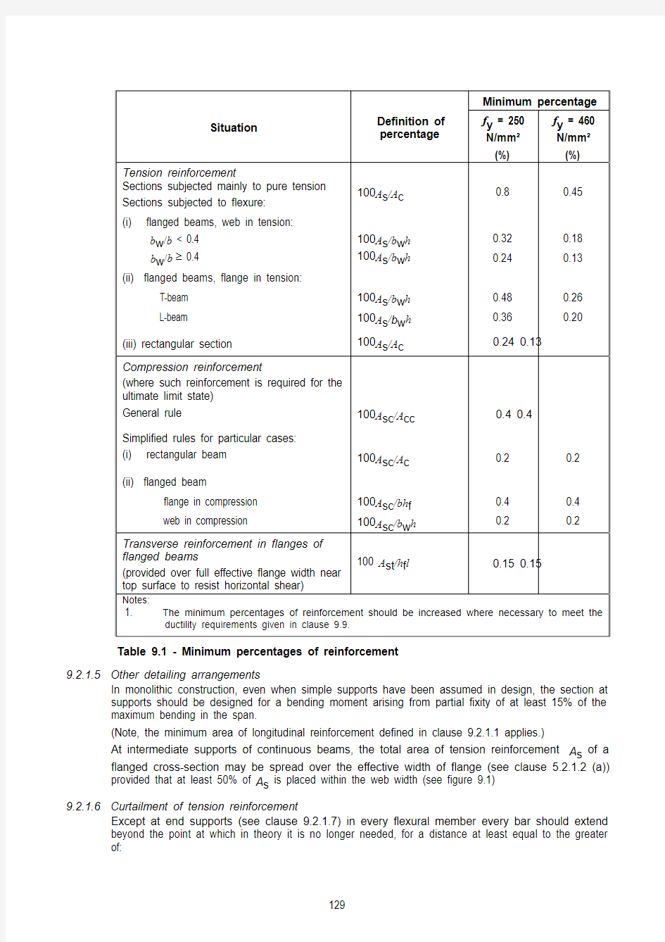
The minimum percentages of reinforcement appropriate for various conditions of loading are given in table 9.1.
Sections containing less reinforcement than that given by table 9.1 should be considered as unreinforced.
9.2.1.2 Side bars for beams exceeding 750 mm overall depth.
The minimum size of longitudinal bars in side faces of beams to control cracking should be not less than √(s b b /f y ) where s b is the bar spacing and b the breadth of the section at the point considered, or 500 mm if b exceeds 500 mm.
The spacing should not exceed 250 mm and the bars should be distributed over a distance of two-thirds of the beam’s overall depth measured from its tension face.
9.2.1.3 Maximum areas of reinforcement
Neither the area of tension reinforcement nor the area of compression reinforcement should exceed 4% of the gross cross-sectional area of the concrete.
At laps, the sum of the reinforcement sizes in a particular layer should not exceed 40% of the breadth of the section at that location.
9.2.1.4 Maximum distance between bars in tension
The clear horizontal distance between adjacent bars, or groups, near the tension face of a beam should not be greater than:
clear spacing ≤ 70 000 βb /f y ≤ 300 mm 9.1 where:
βb is the redistribution ratio:
tion redistribu before section the at moment tion
redistribu after section the at moment from the respective maximum moments diagram. Alternatively, the clear spacing may be assessed from the relationship:
clear spacing ≤ 47 000/f s ≤ 300 mm 9.2 where:
f s is the estimated service stress in the reinforcement and may be obtained from:
b
prov s,req s,y s 1
32β×
=A A f f 9.3
The distance between the face of the beam and the nearest longitudinal bar in tension should not be greater than half the clear distance determined above.
Minimum percentage
Situation Definition of
percentage
f y = 250
N/mm2
(%)
f y = 460
N/mm2
(%)
Tension reinforcement
Sections subjected mainly to pure tension
Sections subjected to flexure:
100A s/A c0.8 0.45 (i) flanged beams, web in tension:
b w/b < 0.4 b w/b≥ 0.4 100A s/b w h
100A s/b w h
0.32
0.24
0.18
0.13
(ii) flanged beams, flange in tension:
T-beam L-beam 100A s/b w h
100A s/b w h
0.48
0.36
0.26
0.20
(iii) rectangular section 100A s/A c0.24 0.13 Compression reinforcement
(where such reinforcement is required for the
ultimate limit state)
General rule 100A sc/A cc0.4 0.4
Simplified rules for particular cases:
(i) rectangular beam 100A
sc/A c0.2 0.2
(ii) flanged beam
flange in compression web in compression 100A sc/bh f
100A sc/b w h
0.4
0.2
0.4
0.2
Transverse reinforcement in flanges of
flanged beams
(provided over full effective flange width near
top surface to resist horizontal shear)
100 A st/h f l0.15 0.15
Notes:
1. The minimum percentages of reinforcement should be increased where necessary to meet the
ductility requirements given in clause 9.9.
Table 9.1 - Minimum percentages of reinforcement
9.2.1.5 Other detailing arrangements
In monolithic construction, even when simple supports have been assumed in design, the section at
supports should be designed for a bending moment arising from partial fixity of at least 15% of the
maximum bending in the span.
(Note, the minimum area of longitudinal reinforcement defined in clause 9.2.1.1 applies.)
At intermediate supports of continuous beams, the total area of tension reinforcement A s of a
flanged cross-section may be spread over the effective width of flange (see clause 5.2.1.2 (a))
provided that at least 50% of A s is placed within the web width (see figure 9.1)
9.2.1.6 Curtailment of tension reinforcement
Except at end supports (see clause 9.2.1.7) in every flexural member every bar should extend
beyond the point at which in theory it is no longer needed, for a distance at least equal to the greater
of:
? the effective depth of the member; or
? 12 times the bar diameter.
In addition for a bar in the tension zone, one of the following distances for all arrangements of design ultimate load should be considered:
? an anchorage length appropriate to its design strength (0.87f y) from the point at which it is no longer required to assist in resisting the bending moment; or
? to the point where the design shear capacity of the section is greater than twice the design shear force at that section; or
? to the point where other bars continuing past that point provide double the area required to resist the design bending moment at that section.
The point at which a bar is no longer required is the point where the design resistance moment of the section, considering only the continuing bars, is equal to the design moment.
As curtailment of substantial areas of reinforcement at a single section can lead to the development of large cracks at that point, it is therefore advisable to stagger the curtailment points in heavily reinforced members.
Figure 9.1 - Placing of tension reinforcement in flanged cross-section
9.2.1.7 Anchorage of bars at a simply-supported end of a beam
At a simply-supported end of a member half the calculated mid-span bottom reinforcement should be anchored by one of the following:
? an effective anchorage length equivalent to 12 times the bar diameter beyond the centre-line of the support. No bend or hook should begin before the centre of the support; or ? an effective anchorage length equivalent to 12 times the bar diameter plus d/2 from the face of the support, where d is the effective depth of member. No bend or hook should
begin before d/2 from the face of the support.
9.2.1.8 Anchorage of bottom reinforcement at internal supports
At an intermediate support of a continuous member 30% of the calculated mid-span bottom reinforcement should be continuous through the support.
9.2.1.9 Cantilever extensions
Where a cantilever forms an extension beyond the end support of a continuous beam or slab, care should be taken to ensure that the top steel in the adjacent span extends beyond the point of contraflexure.
9.2.1.10 Containment of compression reinforcement
The recommendations given in clause 9.5.2 for columns will apply also to beams.
9.2.2 Shear reinforcement
The shear reinforcement may consist of a combination of:
? links enclosing the longitudinal tension reinforcement and the compression zone;
? bent-up bars; and
? cages or ladders (see figure 9.2) which are cast in without enclosing the longitudinal
reinforcement but are properly anchored in the compression and tension zones.
Links should be effectively anchored in accordance with clause 8.5. A lap joint on the leg near the
surface of the web is permitted provided that the link is not required to resist torsion.
At least 50%of the necessary shear reinforcement should be in the form of links.
The minimum area of shear reinforcement for the whole length of a beam is given by:
A sv≥ v r b v s v/(0.87f yv)9.4
where v r is defined in Table 6.2.
The maximum spacing of the links in the direction of the span should not exceed 0.75d. At right-
angles to the span, the horizontal spacing should be such that no longitudinal tension bar is more
than 150 mm from a vertical leg.
The longitudinal spacing of bent-up bars (see figure 6.2) should not exceed s b,max, as given by
equation 9.5.
s b,max = 0.6d(1 + cotα) 9.5 where:
αis the inclination of the bent-up bars to the longitudinal axis.
Figure 9.2 - Examples of shear reinforcement
9.2.3 Torsion reinforcement
Torsion links should be closed and be anchored by means of laps or hooked ends, see figure 9.3,
and should form an angle of 90° with the axis of the structural element.
Figure 9.3 - Torsion link arrangements
Torsion reinforcement should comply with the provisions of clauses 6.3.5 to 6.3.9.
SLABS
9.3 SOLID
This section applies to one-way and two-way solid slabs.
9.3.1 Flexural reinforcement
9.3.1.1 General
(a) Minimum reinforcement
The following minimum percentages of total longitudinal reinforcement should be provided in
each direction:
? f y = 250 N/mm2: 0.24% of concrete cross-sectional area; and
? f y = 460 N/mm2: 0.13% of concrete cross-sectional area.
Generally secondary transverse reinforcement of not less than 20% of the principal
reinforcement should be provided in one-way slabs. In areas near supports transverse
reinforcement to principal top bars is not necessary where there is no transverse bending
moment.
(b) Reinforcement spacing
The maximum spacing of bars should comply with the following requirements:
? for the principal reinforcement, 3h≤ 400 mm; and
? for the secondary reinforcement, 3.5h≤ 450 mm.
In areas with concentrated loads or areas of maximum moment those provisions become
respectively:
? for the principal reinforcement, 2h≤ 250 mm; and
? for the secondary reinforcement, 3h≤ 400 mm.
In addition, unless crack widths are checked by direct calculation, the following rules will
ensure adequate control of cracking for slabs subjected to normal internal and external
environments:
No further check is required on bar spacing if either:
? h≤ 250 mm (grade 250 steel);
? h≤ 200 mm (grade 460 steel); or
? the percentage of required tension reinforcement (100A s/bd) is less than 0.3%.
Where none of these three conditions apply, the bar spacings should be limited to the values
calculated in clause 9.2.1.4 for slabs where the required reinforcement percentage exceeds
1% or the values calculated in clause 9.2.1.4 divided by the reinforcement percentage for
percentage less than 1.
In slabs where the amount of redistribution is unknown, βb may be assumed to be minus 15%
for support moments and zero for span moments.
When reinforcement is needed to distribute cracking arising from shrinkage and temperature
effects, the recommendations given in clause 9.6.5 for plain walls should be followed.
9.3.1.2 Curtailment of tension reinforcement
Curtailing and anchoring reinforcement may be carried out in accordance with clause 9.2.1.6 for beams.
9.3.1.3 Reinforcement at end supports
In simply supported slabs or end support of continuous slabs, half the calculated span reinforcement should be anchored into the support in accordance with section 8.4 and the provisions of clause
9.2.1.7 for beams.
If the design ultimate shear stress at the face of the support is less than half the appropriate value, νc, recommended in clause 6.1.2.5, a straight length of bar beyond the centreline of the support equal to either one-third of the support width or 30 mm, whichever is the greater may be considered as effective anchorage.
Negative moments due to partial fixity may arise which could lead to cracking. To control this, an amount of top reinforcement capable of resisting at least 50% of the maximum mid-span moment, but not less than the minimum given in clause 9.3.1.1, should be provided at the support. It should have a full effective tensile anchorage into the support and extend not less than 0.15l or 45 times the bar diameter into the span.
9.3.1.4 Bottom reinforcement internal supports
At an intermediate support of a slab 40% of the calculated mid-span bottom reinforcement should be continuous through the support.
9.3.1.5 Corner reinforcement
If the detailing arrangements at a support are such that lifting of the slab at a corner is restrained, suitable reinforcement should be provided. See clause 6.1.3.3(c) and (d).
9.3.1.6 Reinforcement at free edges
Along a free (unsupported) edge, a slab should normally contain longitudinal and transverse reinforcement, generally arranged as shown in figure 9.4.
The normal reinforcement provided for a slab may act as edge reinforcement.
Figure 9.4 - Edge reinforcement for a slab
9.3.2 Shear reinforcement
Shear reinforcement, if required for solid slabs, ribbed slabs and flat slabs, should comply with the provisions of clauses 6.1.3.5, 6.1.4.4 or 6.1.5.7 as appropriate.
It is difficult to bend and fix shear reinforcement and assure its effectiveness in slabs less than 200mm thick. Therefore, shear reinforcement should not be used in such slabs.
9.4 CANTILEVERED PROJECTING STRUCTURES
9.4.1 Minimum reinforcement
The minimum percentage of top tension longitudinal reinforcement based on the gross cross-sectional concrete area should be 0.25% for all reinforcement grades. The minimum diameter of this principal reinforcement should be 10 mm.
For areas of minimum reinforcement at other locations within a projecting structure refer to sections
9.2 or 9.3 as appropriate.
9.4.2 Reinforcement spacing
The centre-to-centre spacing of the top tension longitudinal bars should not be more than 150 mm.
9.4.3 Anchorage of tension reinforcement
A full anchorage length should be provided for the top tension reinforcement of a cantilevered
projecting structure. Where full rotational restraint is provided at the near face of the supporting member, i.e. the face at which the bar enters the supporting member, the anchorage shall be deemed to commence at 1/2 the width of the supporting member or 1/2 the effective depth of the cantilevered projecting structure whichever is less, from the near face of the supporting member.
Where the cantilevered projecting structure is a continuous slab or beam and the support is not designed to provide rotational restraint in the analysis of the continuous structure, the anchorage shall be deemed to commence at the far face of the supporting member.
9.5
COLUMNS
This clause deals with columns for which the larger dimension h c is not greater than 4 times the smaller dimension b c.
9.5.1 Longitudinal reinforcement
The area of total longitudinal reinforcement based on the gross cross-sectional area of a column should not be less than 0.8%. See clause 9.9.2 for ductility requirement.
Bars should have a diameter of not less than 12 mm.
The minimum number of longitudinal bars in a column should be four in rectangular columns and six in circular columns. In columns having a polygonal cross-section, at least one bar should be placed at each corner.
The longitudinal reinforcement should not exceed the following amounts, calculated as percentages of the gross cross-sectional area of the concrete:
? vertically-cast columns - 6%;
? horizontally-cast columns - 8%; and
? laps in vertically-or horizontally-cast columns - 10%.
At laps, the sum of the reinforcement sizes in a particular layer should not exceed 40% of the breadth of the section at that location.
reinforcement
9.5.2 Transverse
9.5.2.1 General
The diameter of the transverse reinforcement (links, loops or helical spiral reinforcement) should not be less than 6 mm or 1/4 the diameter of the largest longitudinal bar, whichever is the greater. The diameter of wires or welded mesh fabric when used for transverse reinforcement should not be less than 5 mm.
The spacing of transverse reinforcement along a column should not exceed 12 times the diameter of the smallest longitudinal bar.
9.5.2.2 Rectangular or polygonal columns
Every corner bar, and each alternate bar (or bundle) in an outer layer of reinforcement should be supported by a link passing around the bar and having an included angle of not more than 135° (see figure 9.5a). No bar within a compression zone should be further than 150 mm from a restrained bar.
Links should be adequately anchoraged by means of hooks bent though an angle of not less than 135° (see figure 9.5b).
9.5.2.3 Circular columns
Spiral transverse reinforcement should be anchored by either welding to the previous turn, in accordance with clause 8.7, or by terminating the spiral with at least a 135o hook bent around a longitudinal bar and the hook being no more than 25 mm from the previous turn.
Circular links should be anchored by either a mechanical connection or welded lap, in accordance with clause 8.7, or by terminating each end of the link with at least a 135o hook bent around a longitudinal bar and overlapping the other end of the link (see figure 9.5c).
Spiral or circular links should not be anchored by straight lapping.
Figure 9.5 - Column transverse reinforcement
Where the direction of the column longitudinal bars change, (e.g. at changes in column size), the spacing of transverse reinforcement should be calculated, taking account of the lateral forces involved. These effects may be ignored if the change of direction is less than or equal to 1 in 12.
9.6 WALLS
General
9.6.1
This clause refers to reinforced concrete walls with a length to thickness ratio of 4 or more and in which the reinforcement is taken into account in the strength analysis. For walls subjected predominantly to out-of-plane bending the rules for slabs apply (see section 9.3).
reinforcement
Vertical
9.6.2
The minimum percentage of vertical reinforcement based on the concrete cross-sectional area of a wall is 0.4%. Where this minimum area of reinforcement controls in the design, half of the area should be located at each face.
The area of vertical reinforcement should not exceed 4% of the concrete cross-sectional area of a wall.
The distance between two adjacent vertical bars shall not exceed 3 times the wall thickness or 400 mm whichever is the lesser.
9.6.3 Horizontal reinforcement
Where the main vertical reinforcement is used to resist compression and does not exceed 2% of the concrete area, at least the following percentages of horizontal reinforcement should be provided, depending upon the characteristic strength of that reinforcement:
? f y = 250 N/mm2: 0.30% of concrete cross-sectional area; and
? f y = 460 N/mm2: 0.25% of concrete cross-sectional area.
These horizontal bars should be evenly spaced at no more than 400 mm. The diameter should be not less than one-quarter of the size of the vertical bars and not less than 6 mm.
9.6.4 Transverse reinforcement
When the vertical compression reinforcement exceeds 2%, links at least 6 mm or one-quarter the size of the largest compression bar should be provided through the thickness of the wall. The spacing of links should not exceed twice the wall thickness in either the horizontal or vertical direction. In the vertical direction it should be not greater than 16 times the bar diameter. All vertical compression bars should be enclosed by a link. No bar should be further than 200 mm from a restrained bar, at which a link passes round the bar with an included angle of not more than 90°.
9.6.5 Plain walls
Reinforcement may be needed in plain walls to control cracking due to flexure or thermal and hydration shrinkage. Wherever provided, the minimum quantity of reinforcement in each direction should be at least:
? f y = 250 N/mm2: 0.30% of concrete cross-sectional area; and
? f y = 460 N/mm2: 0.25% of concrete cross-sectional area.
If necessary in walls exceeding 2 m in length and exposed to the weather, reinforcement should be provided in both horizontal and vertical directions. It should consist of small diameter bars, relatively closely spaced, with adequate cover.
For internal plain walls it may be sufficient to provide reinforcement only at that part of the wall where junctions with floors and beams occur. When provided it should be dispersed half near each face.
Nominal reinforcement around openings should be considered.
9.7 FOUNDATIONS
9.7.1 Pile caps
The distance from the outer edge of the pile to the edge of the pile cap should be such that the forces in the pile cap can be properly anchored. The expected deviation of the pile on site should be taken into account.
The main tensile reinforcement to resist the action effects should be concentrated in the stress zones between the tops of the piles. If the area of this reinforcement is at least equal to the minimum reinforcement, evenly distributed bars along the bottom surface of the member may be omitted. Also the sides and the top surface of the member may be unreinforced if there is no risk of tension developing in these parts of the members. The minimum reinforcement as shown in Table
9.1 should be observed.
Welded transverse bars may be used for the anchorage of the tension reinforcement. In this case the transverse bar may be considered to be part of the transverse reinforcement in the anchorage zone of the reinforcement bar considered.
The compression caused by the support reaction from the pile may be assumed to spread at 45° degree angles from the edge of the pile. This compression may be taken into account when calculating the anchorage length.
The compression bond stresses that develop on starter bars within bases or pile caps need not be checked provided:
? the starter bars extend down to the level of the bottom reinforcement;
? the pile cap base has been designed for moments and shear in accordance with section
6.7.
9.7.2 Column and wall footings
The main reinforcement should be anchored in accordance with the requirements of sections 8.4 and 8.5.
If the action effects cause tension at the upper surface of the footing, the resulting tensile stresses should be checked and reinforced as necessary.
The minimum reinforcement as shown in Table 9.1 should be observed.
9.7.3 Tie beams
Tie beams may be used to eliminate the eccentricity of loading of the foundations. The beams should be designed to resist the resulting bending moments and shear forces.
Tie beams should also be designed for a minimum downward load of 10 kN/m if the action of compaction machinery can cause effects to the beams.
9.8
CORBELS
General
9.8.1
The design of corbels may be based on strut-and-tie models provided that equilibrium and strength requirements are satisfied. The horizontal link requirement of clause 9.8.3 will ensure satisfactory serviceability performance.
9.8.2 Reinforcement anchorage
At the front face of the corbel, the reinforcement should be anchored either by:
? welding to a transverse bar of equal strength and diameter. In this case the bearing area of the load should stop short of the transverse bar by a distance equal to the cover of the
tie reinforcement; or
? bending back the bars to form a loop. In this case the bearing area of the load should not project beyond the straight portion of the bars forming the main tension reinforcement.
9.8.3 Shear reinforcement
Shear reinforcement should be provided in the form of horizontal links distributed in the upper 2/3 of the effective depth of the root of the corbel. This reinforcement should not be less than half the area of the main tension reinforcement and should be adequately anchored (see figure 9.6).
Figure 9.6 - Typical corbel detailing
9.8.4 Resistance to horizontal force
Additional reinforcement connected to the supported member should be provided to transmit this force in its entirety.
9.9 DUCTILITY
9.9.1 Beams
9.9.1.1 Longitudinal reinforcement
(a) Maximum and minimum percentages of reinforcement
The minimum percentage of reinforcement in a beam is to be in accordance with table 9.1,
however not less than 0.3%.
The maximum area of tension reinforcement should not exceed 2.5% of the gross cross-
sectional area of the concrete. At any section of a beam within a critical zone the compression
reinforcement should not be less than one-half of the tension reinforcement at the same
section.
(b) Spacing
The maximum clear distance between adjacent bars in tension should not exceed the limits
stated in clause 9.2.1.4.
(c) Anchorage into exterior column
When longitudinal beam bars are anchored in cores of exterior columns or beam stubs, the anchorage for tension shall be deemed to commence at ? of the relevant depth of the column or 8 times the bar diameter whichever is less, from the face at which the beam bar enters the column. Where it can be shown that the critical section of the plastic hinge is at a distance of at least the beam depth or 500 mm, whichever is less, from the column face, the anchorage length may be considered to commence at the column face.
For the calculation of anchorage length the bars must be assumed to be fully stressed.
Notwithstanding the adequacy of the anchorage of a beam bar in a column core or a beam stub, no bar shall be terminated without a vertical 90o standard hook or equivalent anchorage device as near as practically possible to the far side of the column core, or the end of the beam stub where appropriate, and not closer than ? of the relevant depth of the column to the face of entry. Top beam bars shall only be bent down and bottom bars must be bent up.
(d) Splices
Full strength welded splices may be used in any location. For laps and mechanical couplers no portion of the splice shall be located within the beam/column joint region or within one effective depth of the member from the critical section of a potential plastic hinge in a beam where stress reversals in lapped bars could occur.
Reinforcement shall not be lapped in a region where reversing stresses at the ultimate limit state may exceed 0.6f y in tension or compression unless each lapped bar is confined by links or ties so that
yt y
tr f f s A 48φ≥ 9.6 where:
A tr smaller of area of transverse reinforcement within a spacing s crossing a plane of
splitting normal to concrete surface containing extreme tension fibres, or total area of
transverse reinforcement normal to the layers of bars within a spacing s , divided by n ,
mm 2,
s maximum spacing of transverse reinforcement within the lap length,
f yt characteristic yield strength of the transverse reinforcement.
n number of bars uniformly spaced around circular sections, or the number of
longitudinal bars in the layer through which a potential plane of splitting would pass.
Mechanical splices shall be tested through 8 full cycles of loading to a maximum stress of 0.95f y in the bar, and at maximum load in both tension and compression shall show a change of length, measured over the full length of the connection system, not more than 10% in excess of the extension in an equal length of unspliced bar. Splices not satisfying this stiffness requirement shall be used only if they are staggered so that no more than 2/3 of the reinforcement area is spliced within any 900 mm length of the member.
(e) Curtailment
The distribution and curtailment of the longitudinal flexural reinforcement shall be such that the flexural overstrength of a section can be attained at critical sections in potential plastic hinge regions.
9.9.1.2 Transverse reinforcement
(a) Spacing
The centre-to-centre spacing of links or ties along a beam shall not exceed the smaller of the least lateral dimension of the cross section of the beam or 16 times the longitudinal bar diameter.
Links or ties shall be arranged so that every corner and alternate longitudinal bar that is required to function as compression reinforcement shall be restrained by a leg. (b) Anchorage
Links should be adequately anchored by means of 135° or 180° hooks in accordance with
clause 8.5. Anchorage by means of 90° hooks or welded cross bars is not permitted.
9.9.2 Columns
9.9.2.1 Longitudinal reinforcement
(a) Maximum and minimum areas of reinforcement
The area of longitudinal reinforcement based on the gross concrete area of a column shall not
be less than 0.8%.
The area of longitudinal reinforcement for strength design shall not be greater than 4% of the
gross concrete area except that at laps the area may increase to 5.2%.
In any row of bars the smallest bar diameter used shall not be less than 2/3 of the largest bar
diameter used.
When columns are designed to develop plastic hinges in the end regions, the maximum
diameter of column bars passing through the beams shall satisfy:
y cu
f f
h8.0
2.3
≤
φ9.7
where:
h is the overall beam depth.
When columns are not intended to develop plastic hinges in the end regions, the maximum
diameter of longitudinal column bars at any level may exceed that given by equation 9.7 by
25%.
(b) Spacing
For longitudinal bars in potential plastic hinge regions, the cross-linked bars shall not be
spaced further apart between centres than the larger of 1/4 of the adjacent lateral column
dimension or 200 mm.
(c) Anchorage of column reinforcement
Where column bars terminate in beam-column joints or joints between columns and foundation
members and where a plastic hinge in the column may be expected, the anchorage of the
longitudinal column bars into the joint region shall be assumed to commence at ? of the depth
of the beam or 8 bar diameters, whichever is less, from the face at which the column bar
enters the beam or foundation member. When it is shown that a column plastic hinge adjacent
to the beam face cannot occur, the development length shall be considered to commence from
the beam face.
Notwithstanding the adequacy of the anchorage of a column bar into an intersecting beam, no
column bar shall be terminated in a joint area without a horizontal 90o standard hook or
equivalent anchorage device as near the far face of the beam as practically possible, and not
closer than ? of the depth of the beam to the face of entry. Unless a column is designed to
resist only axial forces, the direction of the horizontal leg of the bend must always be towards
the far face of the column.
(d) Splices
Full strength welded splices may be used in any location. For laps and mechanical couplers in
a column the centre of the splice must be within the middle quarter of the storey height of the
column unless it can be shown that plastic hinges cannot develop in the column adjacent to the
beam faces.
Reinforcement shall not be lapped in a region where reversing stresses at the ultimate limit
state may exceed 0.6f y in tension or compression unless each lapped bar is confined by
adequate links or ties (see clause 9.9.1.1d).
9.9.2.2 Transverse reinforcement within critical regions
The extent of critical region in limited ductile high strength reinforced concrete columns shall be from the point of maximum moment over a finite length suggested as follows (including the region influenced by stub effect):
? For 0 < N/(A g f cu) ≤ 0.1, the extent of critical region is taken as 1.0 times the greater dimension of the cross-section or where the moment exceeds 0.85 of the maximum
moment, whichever is larger;
? For 0.1 < N/( A g f cu) ≤ 0.3, the extent of critical region is taken as 1.5 times the greater dimension of the cross-section or where the moment exceeds 0.75 of the maximum
moment, whichever is larger; and
? For 0.3 < N/( A g f cu) ≤ 0.6, the extent of critical region is taken as 2.0 times the greater dimension of the cross-section or where the moment exceeds 0.65 of the maximum
moment, whichever is larger;
where A g is the gross area of section, mm2.
(a) Minimum area of links spirals or cross-ties
The diameter of the transverse reinforcement (links, loops or helical spiral reinforcement)
should not be less than 6 mm or 1/4 the diameter of the largest longitudinal bar, whichever is
the greater.
(b) Spacing
For rectangular or polygonal columns the centre-to-centre spacing of links or cross-ties along a
column shall not exceed the smaller of 1/4 of the least lateral column dimension or 6 times the
diameter of the longitudinal bar to be restrained.
Each longitudinal bar or bundle of bars shall be laterally supported by a link passing around the
bar and having an included angle of not more than 135° (see figure 9.5a).
For circular columns the centre-to-centre spacing of spirals or circular hoops along the column
shall not exceed the smaller of 1/4 of the diameter of the column dimension or 6 times the
diameter of the longitudinal bar to be restrained.
(c) Anchorage
Links should be adequately anchoraged by means of 135° hooks in accordance with clause
9.5.2 (see figure 9.5b & c).
9.9.2.3 Transverse reinforcement outside critical regions
Transverse reinforcement outside critical regions should be in accordance with clause 9.5.2.