Battery Thermal Management in EVs and HEVs
Battery Thermal Management in EVs and HEVs:
Issues and Solutions
Ahmad A. Pesaran
National Renewable Energy Laboratory
1617 Cole Blvd.
Golden, Colorado 80401
Advanced Automotive Battery Conference
Las Vegas, Nevada
February 6-8, 2001
ABSTRACT
Thermal management of batteries in electric vehicles (EVs) and hybrid electric vehicles (HEVs) is essential for effective operation in all climates. This has been recognized in the design of battery modules and packs for pre-production prototype or production EVs and HEVs. Designs are evolving and various issues are being addressed. There are trade-offs between performance, functionality, volume, mass, cost, maintenance, and safety. In this paper, we will review some of the issues and associated solutions for battery thermal management and what information is needed for proper design of battery management systems. We will discuss such topics as active cooling versus passive cooling, liquid cooling versus air cooling, cooling and heating versus cooling only systems, and relative needs of thermal management for VRLA, NiMH, and Li-Ion batteries.
INTRODUCTION
Battery performance, life, and cost directly affect the performance, life, and cost of the electric vehicles (EVs) and hybrid electric vehicles (HEVs). Battery temperature influences the availability of discharge power (for start up and acceleration), energy, and charge acceptance during energy recovery from regenerative braking. These affect vehicle drive-ability and fuel economy. Temperature also affects the life of the battery. Therefore, ideally, batteries should operate within a temperature range that is optimum for performance and life. The desired operating temperature range is different for different battery types (with different electrochemistry). Usually, the optimum temperature range for the battery operation (desired by the battery manufacturer) is much narrower than the specified operating range for the vehicle (identified by the vehicle manufacturer). For example, the desired operating temperature for a lead acid battery is 25°C to 45°C, however the specified vehicle operating range could be -30°C to 60°C.
In addition to considering the (absolute) temperature of a battery pack, uneven temperature distribution in a pack should be also considered. Temperature variation from module to module in a pack could lead to different charge/discharge behavior for each module. This, in turn, could lead to electrically unbalanced modules/packs, and reduced pack performance [1]. For high temperature batteries such as ZEBRA and lithium metal polymer batteries, thermal management is considered an integral part of the battery pack and has been included in the design by the battery manufacturers. The need for battery thermal management for ambient temperature batteries such as valve regulated lead acid (VRLA), nickel metal hydride (NiMH), and lithium
ion (Li-Ion) was not obvious initially, however, EV and HEV battery and vehicle manufacturers have come to realize such a need. Current prototype or production EVs and HEVs with ambient temperature batteries have battery thermal management systems - some more elaborate than others.
Over the last several years, with support from US Department of Energy, NREL has been working with U.S. automobile manufacturers and their battery pack suppliers (as part of the Partnership for a New Generation of Vehicles (PNGV) program) to identify and resolve thermal issues associated with battery packs for HEVs [2]. To evaluate battery pack designs and provide solutions for battery thermal issues, we have used heat transfer and fluid flow principles, finite element thermal analysis, and heat transfer and fluid flow experiments [1, 3, and 5]. We have used thermal imaging techniques and battery calorimetry to measure thermal characteristics of modules and cells in support of battery pack thermal evaluation and design [1, 5, 6, and 7]. Further information on our battery thermal management activities and publications can be found on the Web site https://www.docsj.com/doc/9a18396876.html,/BTM.
In this paper, we will look at various requirements for a battery thermal management system (BTMS) for “ambient temperature” batteries and take a look at trade offs between performance, functionality, volume, mass, cost, maintenance, and safety. We will review some of the issues and associated solutions for battery thermal management and the information that is needed for proper design of battery management systems. We will discuss topics such as active cooling versus passive cooling; liquid cooling versus air cooling; cooling and heating versus cooling only systems; and the relative need of thermal management for VRLA, NiMH, and Li-Ion batteries.
DESIRED ATTRIBUTES OF A THERMAL MANAGEMENT SYSTEM
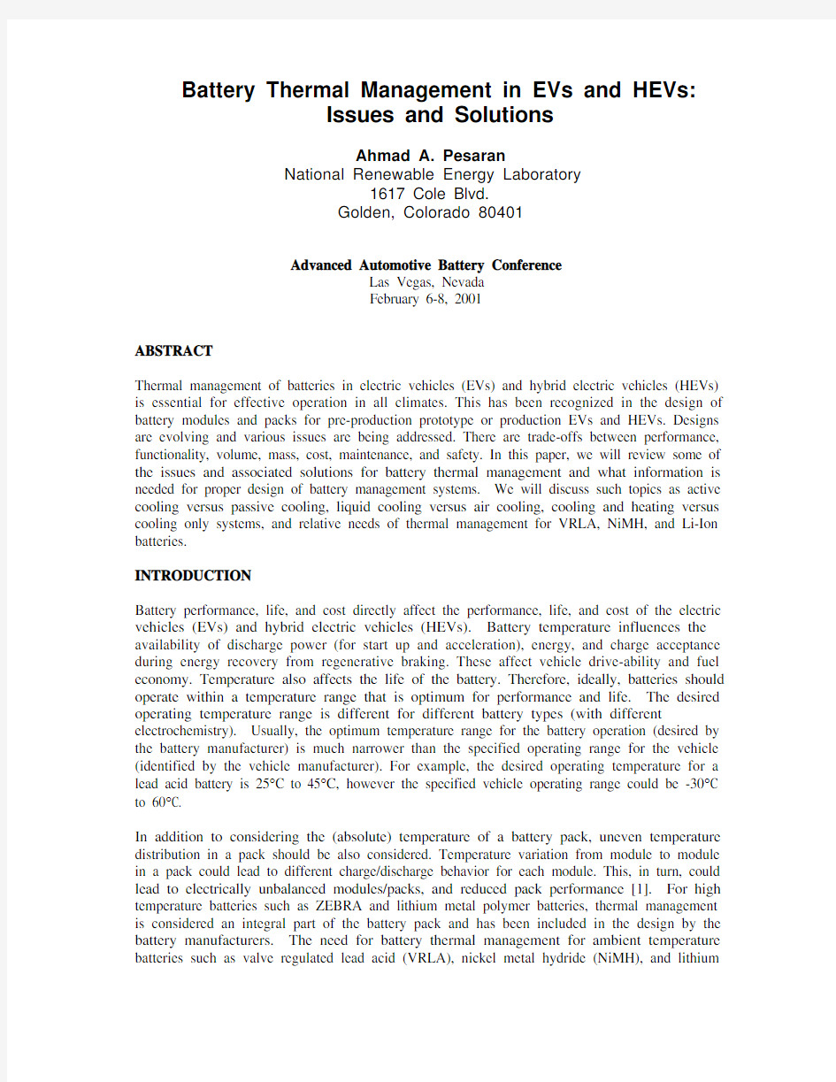
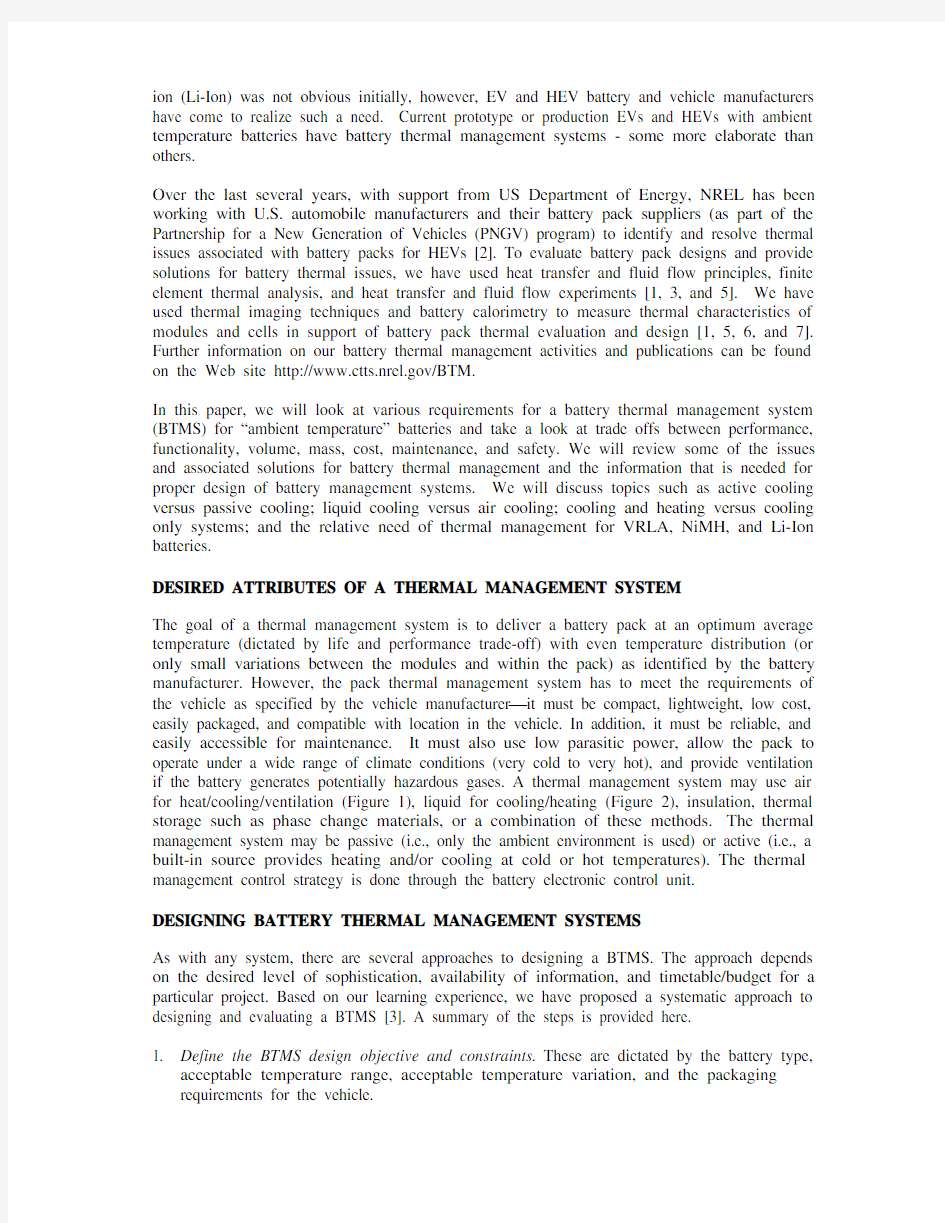
The goal of a thermal management system is to deliver a battery pack at an optimum average temperature (dictated by life and performance trade-off) with even temperature distribution (or only small variations between the modules and within the pack) as identified by the battery manufacturer. However, the pack thermal management system has to meet the requirements of the vehicle as specified by the vehicle manufacturer it must be compact, lightweight, low cost, easily packaged, and compatible with location in the vehicle. In addition, it must be reliable, and easily accessible for maintenance. It must also use low parasitic power, allow the pack to operate under a wide range of climate conditions (very cold to very hot), and provide ventilation if the battery generates potentially hazardous gases. A thermal management system may use air for heat/cooling/ventilation (Figure 1), liquid for cooling/heating (Figure 2), insulation, thermal storage such as phase change materials, or a combination of these methods.The thermal management system may be passive (i.e., only the ambient environment is used) or active (i.e., a built-in source provides heating and/or cooling at cold or hot temperatures). The thermal management control strategy is done through the battery electronic control unit.
DESIGNING BATTERY THERMAL MANAGEMENT SYSTEMS
As with any system, there are several approaches to designing a BTMS. The approach depends on the desired level of sophistication, availability of information, and timetable/budget for a particular project. Based on our learning experience, we have proposed a systematic approach to designing and evaluating a BTMS [3]. A summary of the steps is provided here.
1. Define the BTMS design objective and constraints. These are dictated by the battery type,
acceptable temperature range, acceptable temperature variation, and the packaging requirements for the vehicle.
2. Obtain module/pack heat generation and heat capacity. These will affect the size of the
cooling/heating system and how fast the pack responds to temperature fluctuations.
3. Perform a first-order module and BTMS evaluation. Preliminary analysis is performed to
determine the transient and steady-state thermal response of the module and pack in order to select an initial strategy. Various options, choices of heat transfer medium (air or liquid), and different flow paths (direct or indirect, series or parallel) are evaluated. We believe that to design having a good BTMS starts with a designing a module with thermal behavior in mind.
4. Predict the battery module and pack thermal behavior . Detailed analysis is done to evaluate
the impact of various parameters under various conditions and driving duty cycles for both battery module and pack.
5. Design a preliminary BTMS . Based on the packaging and expected performance, the system
parameters are specified.
6. Build and test the BTMS . A prototype BTMS is built and then tested on the bench and in the
vehicle under various loads and conditions.
7. Improve the BTMS . Based on the test data and analysis, the design is fine tuned or modified
for the next step.
A. Passive Cooling – Outside Air Ventilation
B. Passive Heating and Cooling – Cabin Air Ventilation
C. Active Heating and Cooling – Outside or Cabin Air
Figure 1. General Schematic of Thermal Management using Air
Exhaust Fan
Exhaust cores
Exhaust
D. Passive Cooling – Liquid Circulation
E. Active Moderate Cooling/Heating – Liquid Circulation
F. Active Cooling and Heating – Liquid Circulation
Figure 2. General Schematic of Thermal Management using Liquid
Liquid/air heat exchanger Fan Liquid direct-contact or indirect Liquid/liquid heat exchanger Pump coolant Liquid direct-contact or indirect or Refrigerant from Condenser Liquid/liquid heat exchanger Pump coolant AC Heat Exchanger
Liquid direct-contact or indirect
DISCUSSION
In the following sections, we discuss a selected number of battery thermal management issues of interest to the community and organizers of the conference.
Heat Generation and Heat Capacity
The magnitude of the overall heat generation rate from a battery pack under load dictates the size and design of the cooling system. The heat generation (due to electrochemical enthalpy change and electrical resistive heating) depends on the chemistry type, construction, temperature, state
of charge, and charge/discharge profile. At NREL, we have been using a large custom-built calorimeter to measure the heat generation from cells/modules with various cycles, state of charge, and temperature [3, 7, and 8]. Table 1 shows some typical results for various batteries. These and other data show that that, for the same current draw, a NiMH battery generates more heat than a VRLA or Li-Ion batteries at elevated temperatures (> 40°C). Heat generation from VRLA and Li-Ion is roughly the same for similar currents. At room temperature, less heat is generated for NiMH for the same current, but NiMH is not as energy efficient. Generally, as temperature decreases more heat is generated because of an increase in resistance in the cells. As the discharge rate increases, more heat is generated. Under certain conditions, the battery electrochemical reaction could be endothermic, as shown in Table 1 for Li-Ion battery at C/1 discharge rate at 50°C.
Table 1. Heat generation from Typical HEV/EV Modules using NREL’s Calorimeter
[7and 8]
Heat Generation (W)/Cell Battery Type Cycle 0°C 22-25°C 40-50°C
1.21 1.28 0.4 VRLA, 16.5 Ah C/1 Discharge, 100% to 0% State of
Charge
16.07 14.02 11.17 VRLA, 16.5 Ah 5C Discharge, 100% to 0% State of
Charge
NiMH, 20 Ah C/1 Discharge, 70% to 35% State of
- 1.19 1.11 Charge
- 22.79 25.27 NiMH, 20 Ah 5C Discharge, 70% to 35% State of
Charge
Li-Ion, 6 Ah C/1 Discharge, 80% to 50% State of
0.6 0.04 -0.18
Charge
12.07 3.50 1.22 Li-Ion, 6 Ah 5C Discharge, 80% to 50% State of
Charge
In order to do any reasonable transient thermal analysis, the designer needs to know the heat capacity of a module in order to determine the thermal mass of the pack. Overall or average heat capacity can either be measured in a calorimeter [7 and 8] or calculated from knowledge of the heat capacity of individual components using a mass-weighted average of cell/module components. Typical heat capacity for a VRLA (16.5 Ah) is 660 J/kg/K, for a NiMH (20 Ah) heat capacity is 677.4 J/kg/K, and for Li-Ion (6 Ah) heat capacity is 795 J/kg/K. Figure 3 shows the impact of heat generation and heat capacity on the temperature rise of a selected EV module using air-cooling.
Module Temperature Distribution
The design of a battery cell/module dictates its temperature distribution. The heat generation in a module may not be spatially uniform due to several factors: aspect ratio, number of cells and
geometry, thermal conductivity of the case, placement of the positive and negative terminals, size and position of the cell interconnects within the module, and spatial variation of current density within a cell. Non-uniform heat generation could lead to non-uniform temperature distribution in the module.
Figure 3. Transient Temperature Rise in a Module with Constant Heat Generation
As an example, thermal images of a 6-cell Optima lead acid HEV battery with terminals on the same side indicated a modest variation in axial heat generation and a 20°C temperature distribution in the Optima lead acid HEV module [5]. On the other hand, Saft high-power lithium ion cells with a hollow core for cooling, terminal placements at both ends, and high thermal-conductivity of the active material and the case material achieved a relatively uniform temperature distribution with variation of less than 2°C [6]. Ovonic Battery Company has recently integrated liquid cooling within their high-power NiMH modules (Figure 4) by jacket cooling each cell to achieve uniform temperature distribution in a module in addition to better temperature control.
Figure 4. Water Cooled Ovonic NiMH Module
(10 cells, 12 V, 12 Ah, 48 Whr/kg, 550 W/kg)
2
4
68101214
16
0400800120016002000Time (seconds)
T e m p e r a t u r e R i s e (D e g r e e C )
Air Cooling versus Liquid Cooling
Choice of heat transfer medium has a significant impact on the performance and cost of the battery thermal management system. The heat transfer medium could be air, liquid, phase change material, or any combination. Heat transfer with air is achieved by directing/blowing the air across the modules (Figure 1). However, heat transfer with liquid could be achieved either through discrete tubing around each module; with a jacket around the module; submerging modules in a dielectric fluid for direct contact; or placing the modules on a liquid heated/cooled plate (heat sink). If the liquid is not in direct contact with modules, such as in tubes or jackets, the heat transfer medium could be water/glycol or even refrigerants, which are common automotive fluids. If modules are submerged in the heat transfer liquid, the liquid must be dielectric, such as silicon-based or mineral oils, to avoid any electrical shorts.
Using the air as the heat transfer medium may be the simplest approach, but it may not be as effective as heat transfer by liquid. The rate of heat transfer between the walls of the module and the heat transfer fluid depends on the thermal conductivity, viscosity, density, and velocity of the fluid. For the same flow rate, the heat-transfer rate for most practical direct-contact liquids such as oil is much higher than with air because of the thinner boundary layer and higher fluid thermal conductivity. However, because of oil’s higher viscosity and associated higher pumping power, a lower flow rate is usually used, making the oil heat transfer coefficient only 1.5 to 3 times higher than with air. Indirect-contact heat transfer liquids such as water or water/glycol solutions generally have lower viscosity and higher thermal conductivity than most oils, resulting in higher heat transfer coefficients. However, because the heat must be conducted through walls of the jacket/container or fins, indirect contact effectiveness decreases.
For example, in one of our previous studies, we compared air with direct liquid (oil) cooling for VRLA modules in a pack. Based on cooling need and pressure drop considerations, we selected an air mass through flow rate of 50 g/s, which at atmospheric conditions (25 o C) has a volumetric flow rate of 43 L/s. Using the classic correlation for turbulent flows, the average heat transfer rate was 25 W/m2K. An equal mass flow rate of a mineral oil had a volumetric flow rate of only 0.057 L/s, resulting in an average heat transfer rate of 57 W/m2K (2.3 times higher than air). The same mass flow rate using water for indirect cooling could have resulted in a volumetric flow rate of 0.049 L/s and a heat transfer rate of 390 W/m2Kfor indirect cooling, but one must also consider heat transfer resistance of containment walls which reduces effective heat removal. Using the finite element analysis and non-uniform heat generation, we obtained the transient and steady state thermal performance for a 12-V, 6-cell HEV VRLA module using air and liquid cooling. Figure 5 shows the maximum temperature at the top, middle, and bottom of the cell versus time for air-cooling and oil cooling, respectively. Note that the module in the oil-cooling case is cooler and reaches steady state much more quickly than the air-cooling case because of the higher heat transfer rate of liquid (higher thermal conductivity of oil). An interesting observation is that the temperature gradient in the cell core remained about the same for either air cooling or liquid cooling; this results from the dominant effect of non-uniform axial heat generation within the module. This means that the construction and design of the module play an important rule on how it performs thermally. Inter-cell cooling may be required for better thermal performance. That is why Ovonic Battery Company is liquid cooling each individual cell using a serpentine design rather than jacket cooling the whole module as others have done in the past. Although liquid cooling/heating is more effective and takes up less volume, it has its drawbacks. It could have more mass, has a potential for leaks, need more components (comparing Figures 1 and 2), and could cost more. Maintenance and repair of a liquid cooled pack is more involved and costlier. Indirect liquid cooling, with either jackets or cold plate is easier to handle than direct liquid cooling.
Figure 5. Transient and steady-state comparison of cooling an Optima module with liquid or air based on a similar parasitic pump/fan power (The top, middle, and bottom refer to the
vertical location of the modules.)
T top,SS = 45 o
C Top Middle Bottom
Oil Cooled
Heat generation = 30 W/module Initial module temp. = 30 o C Inlet oil temp. = 25 o C
0102030405060
Time [min]
30
3540455055
M a x . C e l l T e m p e r a t u r e [o C ]Air Cooled Heat generation = 30 W/module Initial module temp. = 30 o C T top,SS = 54 o
C Bottom Middle Top Inlet air temp. = 25 o C
0102030405060
Time [min]
30
35
40
455055
M a x . C e l l T e m p e r a t u r e [o C ]
Active versus Passive Systems
Because of cost, mass, and space considerations and their use in mild climates, battery packs in early vehicles, particularly EVs, did not use heating or cooling units and depended on blowing ambient air for rejection of heat from the batteries (Figure 1.A). Early prototype HEVs also used passive ambient air-cooling. Current production HEVs (Honda Insight and Toyota Prius) use cabin air for cooling/heating of the pack. Although the ambient air is heated and cooled by the vehicle air conditioning (AC) or heating system, it is still considered to be a passive system. Figure 2.D shows a passive liquid system that uses ambient air for heat rejection. For these passive systems, the ambient air must have a mild temperature (10°C-35°C) for the thermal management to work; otherwise the pack performance can suffer in very cold or very hot conditions. Outside of these conditions, active components such as evaporators, heating cores, engine coolant, or even electric and fuel-fired heaters are needed.
Cooling Only Systems versus Cooling and Heating Systems
EVs were initially aimed for the mild to warm climate of California. The battery performance is generally better at higher temperature; however, life can get shorter with higher temperature. So batteries in these EVs needed to be cooled only, and there was no need for too much heating. At cold temperatures (below –10°C), the energy and power capability of most batteries diminishes and EV and HEV performance diminishes. Heating systems have been used for EVs operating at colder climates. For EVs, there is no engine to aid in heating the battery pack, so the heat rejected from motor and power electronics and electricity from the battery could be used for electric heating; otherwise, a fuel-fired heater could be considered. For HEVs the heat from engine could be used, however, it takes some time (more than 5 minutes) for the engine to start warming the batteries. However, because power from the battery is needed much sooner, self-heating battery technology is an option that needs further investigation.
Cooling the batteries is a less challenging task than heating since the vehicle air conditioning/ refrigerant system or engine coolant could be used. However, energy use increases with use of refrigeration, which is contrary to the HEV goal of improving fuel economy.
Series versus Parallel Air Distribution
There are two methods for distributing air to a pack for cooling and/or heating. The first method is series cooling, where air enters from one end of the pack and leaves from the other, exposing the same amount of air to several modules. The second method is parallel cooling, where the same total airflow rate is split into equal portions, and each portion flows over a single module. Depending on the size and geometry of the modules, series-parallel combination could be configured. We have found that parallel airflow provided a more even temperature distribution among the modules in the pack [1 and 3]. EV packs in GM EV1, Toyota RAV4-EV, Honda Insight HEV, and Toyota Prius (Japanese version) all have either series or series-parallel air distribution. The Toyota Prius (North American version) uses a pure parallel air distribution system or even temperature distribution. In parallel flow design, distributing airflow uniformly to a large battery pack will require a careful design of the air manifold.
Thermal Management for VRLA, NiMH, and Li-Ion Batteries
The relative need of the thermal management of each of the VRLA, NiMH, Li-Ion batteries depends on the heat generation rate from each type of battery, its energy efficiency, and the sensitivity of performance to temperature. From Table 1, it can be seen that NiMH batteries generate the most heat t high temperatures (>40°C) and are least efficient. At room temperature, NiMH generates less heat than VRLA and Li-Ion. The performance of a NiMH battery is more sensitive to temperature than VRLA and Li Ion batteries. Therefore, NiMH batteries need a more involved battery management control. This is also evident from various efforts to use the more effective liquid cooling for NiMH batteries. The concerns for Li Ion packs are safety and
relatively poor performance at very cold temperatures. Since Li Ion batteries can deliver much more power and thus more heat for the same volume than either VRLA or NiMH, heat removal needs to be efficient. Thermal management also depends on the type of vehicle and where the pack will be located. For EV and series HEV, the pack is generally large and its thermal management system may need to be more elaborate, possibly incorporating liquid cooling, particularly for NiMH. However, for parallel HEVs, the pack is generally smaller and the thermal control could be achieved by a simpler air cooling/heating design, especially for Li Ion and VRLA.
CONCLUSIONS
A well-designed thermal management system is required to regulate EV and HEV battery pack temperatures evenly, keeping them within the desired operating range. Production HEVs require an active heating/cooling BTMS to allow them to operate in hot and cold climates. Proper thermal design of a module has a positive impact on overall pack thermal management and its behavior. A thermal management system using air as the heat transfer medium is less complicated, though less effective, than a system using liquid cooling/heating. Generally, for parallel HEVs, an air thermal management system is adequate, whereas for EVs and series HEVs, liquid-based systems may be required for optimum thermal performance. NiMH batteries require a more elaborate thermal management system than Li Ion and VRLA batteries. Li Ion batteries also need a good thermal management system because of safety and low temperature performance concerns. The location of the battery pack may also have a strong impact on the type of battery thermal management and whether the pack should be air cooled or liquid cooled. ACKNOWLEDGMENTS
This work was supported by DOE’s Hybrid Vehicle Propulsion Program. The author wishes to acknowledge the support of DOE program manager, Bob Kost, and the NREL HEV technology manager Terry Penney. The author also appreciates the efforts of Matt Keyser and Mark Mihalic of NREL for conducting thermal characterization/evaluation of many battery modules and packs. REFERENCES
1. Pesaran, A.A., Vlahinos, A., Burch, S.D., "Thermal Performance of EV and HEV Battery Modules and Packs,"
Proceedings of the 14th International Electric Vehicle Symposium, Orlando, Florida, December 15–17, 1997.
2. Oswald, L.J. and Skellenger, G.D. "The GM/DOE Hybrid Vehicle Propulsion Systems Program: A Status
Report,” Proceedings of the 14th International Electric Vehicle Symposium, Orlando, Florida, December 15–17, 1997.
3. Pesaran, A.A., Burch, S.D., Keyser, M., “An Approach for Designing Thermal Management Systems for Electric
and Hybrid Vehicle Battery Packs,” May 24-27, 1999, Proceedings of the 4th Vehicle Thermal Management Systems, London, UK.
4. Pesaran, A.A., Russell, D.J., Crawford, J.W., Rehn, R., and. Lewis,E.A.,"A Unique Calorimeter-Cycler for
Evaluating High-Power Battery Modules," Proceedings of the 13th Annual Battery Conference: Applications and Advances, Long Beach, California, January 13–16, 1998.
5. Pesaran, A.A., Swan, D., Olson, J., Guerin, J.T., Burch, S., Rehn, R., Skellenger, G.D., "Thermal Analysis and
Performance of a Battery Pack for a Hybrid Electric Vehicle," Proceedings of the 15th International Electric Vehicle Symposium, Brussels, Belgium, October 1–October 3, 1998.
6. Keyser, M., Pesaran, A.A., Oweis, S. Chagnon, G., Ashtiani, C. “Thermal Evaluation and Performance of High-
Power Lithium-Ion Cells,” in Proceedings of the 16th International Electric Vehicle Symposium, Beijing, China, October 1–3, 1999.
7. Pesaran, A.A., Keyser, K.,"Thermal Characteristics of selected EV and HEV Batteries,” Proceedings of the 16th
Annual Battery Conference: Applications and Advances, Long Beach, California, January 9–12, 2001.
8. Keyser, M., Pesaran, A.A., Mihalic, A., and Zolot, M, “ Thermal Characterization of Advanced Battery
Technologies for EV and HEV Applications,” NREL Report, August 2000.
视觉测量系统技术及应用
视觉测量系统技术及应用 1 引言 基于计算机的视觉检测系统是指通过计算机视觉产品将被摄取目标转换成图像信号,传送给图像处理系统,图像处理系统再根据像素分布和亮度、颜色等信息,转变成数字化信号,计算机图像系统对这些信号进行复杂运算来抽取目标的特征,进而根据判别的结果来控制设备动作。它具有非接触、速度快等优点,是一种先进的检测手段,非常适合现代制造业。可用于视觉检测的试验原理很多,如纹理梯度法、莫尔条纹法、飞行时间法等,然而诸多测试原理中,尤其基于三角法的主动和被动视觉测量原理具有抗干扰能力强、效率高、精度合适等优点,非常适合在线非接触测量。本文主要从视觉测量系统在实际中应用出发,展示视觉检测技术在制造业中的广阔应用[1-4]。 2 视觉测量系统技术的应用 2.1 汽车车身视觉检测系统 在汽车制造过程中,车身上总有很多关键的三维尺寸进行测量,采用传统的三坐标测量机只能离线抽样检测,效率低,更不能满足现代汽车制造在线检测的需要,而视觉检测系统能很好的适应该需要,典型的汽车车身视觉检测系统如图1所示[5]。 图1 车身视觉检测系统 车身检测系统主要依靠的是数个视觉传感器,其中还包括传送机构、定位机构,计算机图像采集、网络控制部分。每个传感器对应一个被测区域,然后通过传输总线传至计算机,通过计算机对每个视觉传感器进行过程控制。 汽车车身检测系统的测量效率很高,精度式中,并且可以在完全自动情况下完成,这个包含几十个测点的系统都能再几分钟内测量完成,因此可以适应汽车制造的在线检测。而且传感器的布置可以根据不同车型来布置,增加了应用要求,
因此减少了车身视觉系统的维护费用。 2.2 拔丝模孔形视觉检测系统 使用计算机视觉检测技术开发出的拔丝模孔形检测系统由光学成像系统、工业用摄像机图像采集卡、计算机及监视器组成,可以解决生产实际中的模具孔形检测问题.工作原理如下:先采用注入硅胶方法获得反映待检拔丝模尺寸及形状的硅胶凸模,然后把硅胶凸模放在光学系统的载物台上.硅胶凸模经光学成像放大,成像于CCD像面上,然后用图像采集卡采集CCD图像信息,最后由计算机视觉检测软件完成对孔形尺寸的自动计算,此时图像采集时需要配置特殊的光照系统.系统实现了自动数据采集、处理,实现采样、进样、结果一条龙,形成检测的自动化. 2.3 无缝钢管直线度和截面在线视觉检测 无缝钢管是一类重要的工业产品,在反应无缝钢管质量中,钢管直线度及截面尺寸是主要的几何参数。现代工业已经可以实现无缝钢管的大批量大规模生产,并且并无成熟的直线度、截面尺寸高效率的检测系统,主要原因为:无缝钢管空间尺寸大,需要很大的测量空间,一般的检测手段很难实现如此大尺度的检测。然而视觉检测却非常适合无缝钢管及截面尺寸的测量,其测量原理图如图2所示。 多个传感器组成了视觉检测系统,传感器的结构光所投射的光平面与被测钢管相交,从而得到钢管的部分圆周,传感器测量圆周在传感器三维空间位置,每一个传感器实现一个截面圆周测测量,然后通过拟合得到截面的圆心和其空间位置,从而实现对无缝钢管截面和直径的测量。 图2 无缝钢管在线检测 2.4 视觉测量在逆向工程中的应用 逆向工程是针对现有的工件,利用3D数字化测量仪准确快速地测量出轮廓坐标值,并建构曲面,经过编辑、修改后,将图形存档形成一般的CAD/CAM系统,再由CAM所产生刀具的NC加工路径送至CNC加工机制所需模具,或者以快速成型将物品模型制作出来。视觉测量一般使用三种激光光源:点结构光、线结构光、面结构光,图3为使用线结构光测量物体表面轮廓的结构示意图[6]。
视觉检测系统报告
视觉检测系统报告 年春季学期研究生课程考核(阅读报告、研究报告)考核科目:视觉测量系统学所在院(系):电气工程及自动化学院学生所在学科:仪器科学与技术学生姓名:***学 号:10S001***学生类别:工学硕士考核结果: 阅卷人: 视觉测量系统课程报告第一部分视觉测量系统发展现状综述机器视觉自起步发展到现在,已有15年的发展历史。应该说机器视觉作为一种应用系统,其功能特点是随着工业自动化的发展而逐渐完善和发展的。 目前全球整个视觉市场总量大概在60~70亿美元,是按照每年 8、8%的增长速度增长的。而在中国,这个数字目前看来似乎有些庞大,但是随着加工制造业的发展,中国对于机器视觉的需求将承上升趋势。 一、机器视觉的定义及特点简言之,机器视觉就是用机器代替人眼来做测量和判断。机器视觉系统是指通过机器视觉产品(即图像摄取装置,分CMOS和CCD两种)将被摄取目标转换成图像信号,传送给专用的图像处理系统,根据像素分布和亮度、颜色等信息,转变成数字化信号;图像系统对这些信号进行各种运算来抽取目标的特征,进而根据判别的结果来控制现场的设备动作。
机器视觉系统的特点是提高生产的柔性和自动化程度。在一些不适合于人工作业的危险工作环境或人工视觉难以满足要求的场合,常用机器视觉来替代人工视觉;同时在大批量工业生产过程中,用人工视觉检查产品质量效率低且精度不高,用机器视觉检测方法可以大大提高生产效率和生产的自动化程度。而且机器视觉易于实现信息集成,是实现计算机集成制造的基础技术。 正是由于机器视觉系统可以快速获取大量信息,而且易于自动处理,也易于同设计信息以及加工控制信息集成,因此,在现代自动化生产过程中,人们将机器视觉系统广泛地用于工况监视、成品检验和质量控制等领域。在中国,这种应用也在逐渐被认知,且带来最直接的反应就是国内对于机器视觉的需求将越来越多。 二、机器视觉在国内外的应用现状在国外,机器视觉的应用普及主要体现在半导体及电子行业,其中大概40%~50%都集中在半导体行业。具体如PCB印刷电路:各类生产印刷电路板组装技术、设备;单、双面、多层线路板,覆铜板及所需的材料及辅料;辅助设施以及耗材、油墨、药水药剂、配件;电子封装技术与设备;丝网印刷设备及丝网周边材料等。SMT表面贴装:SMT工艺与设备、焊接设备、测试仪器、返修设备及各种辅助工具及配件、SMT材料、贴片剂、胶粘剂、焊剂、焊料及防氧化油、焊膏、清洗剂等;再流焊机、波峰焊机及自动化生产线设备。电子生产加工设备:电子元件制造设备、半导体及集成电路制造设备、元
视觉检测原理介绍
技术细节 本项目应用了嵌入式中央控制及工业级图像高速传输控制技术,基于CCD/CMOS与DSP/FPGA的图像识别与处理技术,成功建立了光电检测系统。应用模糊控制的精选参数自整定技术,使系统具有对精确检测的自适应调整,实现产品的自动分选功能。 图1 控制系统流程图 光电检测系统主要通过检测被检物的一些特征参数(灰度分布,RGB分值等),从而将缺陷信息从物体中准确地识别出来,通过后续的系统进行下一步操作,主要分为以下几部分 CCD/CMOS图像采集部分 系统图像数据采集处理板中光信号检测元件CCD/CMOS采用进口的适合于高精度检测的动态分析单路输出型、保证实际数据输出速率为320MB/s的面阵CCD/CMOS。像素分别为4000*3000和1600*1200,帧率达到10FPS。使用CCD/CMOS 作为输入图像传感器,从而实现了图像信息从空间域到时间域的变换。为了保证所需的检测精度,需要确定合理的分辨率。根据被检测产品的大小,初步确定系统设计分辨率为像素为0.2mm。将CCD/CMOS接收的光强信号转换成电压幅值,再经过A/D转换后由DSP/ FPGA芯片进行信号采集,即视频信号的量化处理过程,图像采集处理过程如图所示:
图2 图像采集处理过程 数据处理部分 在自动检测中,是利用基于分割的图像匹配算法来进行图像的配对为基础的。图像分割的任务是将图像分解成互不相交的一些区域,每一个区域都满足特定区域的一致性,且是连通的,不同的区域有某种显著的差异性。分割后根据每个区域的特征来进行图像匹配,基于特征的匹配方法一般分为四个步骤:特征检测、建立特征描述、特征匹配、利用匹配的“特征对”求取图像配准模型参数。 算法基本步骤如下: 1)利用图像的色彩、灰度、边缘、纹理等信息对异源图像分别进行分割,提取区域特征; 2)进行搜索匹配,在每一匹配位置将实时图与基准图的分割结果进行融合,得到综合分割结果; 3)利用分割相似度描述或最小新增边缘准则找出正确匹配位置。 设实时图像分割为m个区域,用符号{A1,A2,… Am}表示,其异源基准图像分割为n个区域,用符号{B1,B2,…Bn}表示。分割结果融合方法如下: 在每一个匹配位置,即假设的图像点对应关系成立时,图像点既位于实时图中,又位于其异源基准图像中,则融合后区域点的标识记为:(A1B1,A1B2,…,A2B1,A2B2,…)。标识AiBj表示该点在实时图中位于区域i,在基准图中位于区域j。算法匹配过程如下图所示:
机器视觉测量技术
机器视觉测量技术 杨永跃 合肥工业大学 2007.3
目录第一章绪论 1.1 概述 1.2 机器视觉的研究内容 1.3 机器视觉的应用 1.4 人类视觉简介 1.5 颜色和知觉 1.6 光度学 1.7 视觉的空间知觉 1.8 几何基础 第二章图像的采集和量化 2.1 采集装置的性能指标 2.2 电荷藕合摄像器件 2.3 CCD相机类 2.4 彩色数码相机 2.5 常用的图像文件格式 2.6 照明系统设计 第三章光学图样的测量 3.1 全息技术 3.2 散斑测量技术 3.3 莫尔条纹测量技术 3.4 微图像测量技术 第四章标定方法的研究 4.1 干涉条纹图数学形成与特征 4.2 图像预处理方法 4.3 条纹倍增法 4.4 条纹图的旋滤波算法 第五章立体视觉 5.1 立体成像
5.2 基本约束 5.3 边缘匹配 5.4 匹域相关性 5.5 从x恢复形状的方法 5.6 测距成像 第六章标定 6.1 传统标定 6.2 Tsais万能摄像机标定法 6.3 Weng’s标定法 6.4 几何映射变换 6.5 重采样算法 第七章目标图像亚像素定位技术 第八章图像测量软件 (多媒体介绍) 第九章典型测量系统设计分析9.1 光源设计 9.2 图像传感器设计 9.3 图像处理分析 9.4 图像识别分析 附:教学实验 1、视觉坐标测量标定实验 2、视觉坐标测量的标定方法。 3、视觉坐标测量应用实验 4、典型零件测量方法等。
第一章绪论 1.1 概述 人类在征服自然、改造自然和推动社会进步的过程中,面临着自身能力、能量的局限性,因而发明和创造了许多机器来辅助或代替人类完成任务。智能机器或智能机器人是这种机器最理想的模式。 智能机器能模拟人类的功能、能感知外部世界,有效解决问题。 人类感知外部世界:视觉、听觉、嗅觉、味觉、触觉 眼耳鼻舌身 所以对于智能机器,赋予人类视觉功能极其重要。 机器视觉:用计算机来模拟生物(外显或宏观)视觉功能的科学和技术。 机器视觉目标:用图像创建或恢复现实世界模型,然后认知现实世界。 1.2 机器视觉的研究内容 1 输入设备成像设备:摄像机、红外线、激光、超声波、X射线、CCD、数字扫描仪、 超声成像、CT等 数字化设备 2 低层视觉(预处理):对输入的原始图像进行处理(滤波、增强、边缘检测),提取角 点、边缘、线条色彩等特征。 3 中层视觉:恢复场景的深度、表面法线,通过立体视觉、运动估计、明暗特征、纹理 分析。系统标定 4 高层视觉:在以物体为中心的坐标系中,恢复物体的完整三维图,识别三维物体,并 确定物体的位置和方向。 5 体系结构:根据系统模型(非具体的事例)来研究系统的结构。(某时期的建筑风格— 据此风格设计的具体建筑) 1.3 机器视觉的应用 工业检测—文件处理,毫微米技术—多媒体数据库。 许多人类视觉无法感知的场合,精确定量感知,危险场景,不可见物感知等机器视觉更显其优越十足。 1 零件识别与定位
机器视觉检测分解
研究背景: 产品表面质量是产品质量的重要组成部分,也是产品商业价值的重要保障。产品表面缺陷检测技术从最初的依靠人工目视检测到现在以CCD 和数字图像处理技术为代表的计算机视觉检测技术,大致经历了三个阶段,分别是传统检测技术阶段、无损检测技术阶段、计算机视觉检测技术阶段。[] 传统检测技术 (1)人工目视检测法 (2)频闪检测法 无损检测技术 (1)涡流检测法 (2)红外检测法 (3)漏磁检测法 计算机视觉检测技术 (1)激光扫描检测法 (2)CCD 检测法 采用荧光管等照明设备,以一定方向照射到物体表面上,使用CCD摄像机来扫描物体表面,并将获得的图像信号输入计算机,通过图像预处理、缺陷区域的边缘检测、缺陷图像二值化等图像处理后,提取图像中的表面缺陷的相关特征参数,再进行缺陷图像识别,从而判断出是否存在缺陷及缺陷的种类信息等。 优点:实时性好,精确度高,灵活性好,用途易于扩充,非接触式无损检测。 基于机器视觉的缺陷检测系统优点: 集成化生产缩短产品进入市场时间改进生产流程100%质量保证实时过程监控提高产量精确检测100%检测 由于经济和技术原因国内绝大多数图像处理技术公司都以代理国外产品为主,没有或者很少涉足拥有自主知识产权的机器视觉在线检测设备,对视觉技术的开发应用停留在比较低端的小系统集成上,对需要进行大数据量的实时在线检测的研究很少也很少有成功案例,但是随着国内经济发展和技术手段不断提高对产品质量检测要求就更高,对在线检测设备的需求也就更大具有巨大的市场潜力。 机器视觉图像处理技术是视觉检测的核心技术 铸件常见缺陷:砂眼气孔缩孔披缝粘砂冷隔掉砂毛刺浇不足缺陷变形 问题的提出: 1.水渍、污迹等不属于铸件缺陷,但由于其外观形貌与缺陷非常类似, 因此易被检测系统误识为缺陷。从目前发表的文献来看,对于伪缺陷的识别率较低。 2.不同种缺陷之间可能存在形状、纹理等方面的相似性,造成缺陷误判。 国外研究发展现状: 20 世纪90 年代后,基于机器视觉检测系统的自动化功能和实用化水平得到了进一步的提高。 1990 年芬兰Rautaruukki New Technology公司研制了Smartivis表面检测系统[],该系统具有自学习分类功能,应用机器学习方法对决策树结构进行自动设计优化。 1996 年美国Cognex公司研发了一套iLearn自学习分类器软件系统并应用于其研制了iS-2000 自动检测系统。通过这两套系统的无缝衔接,极大地提高了检测系统实时的运算速度,有效的改进了传统自学习分类方法在算法执行速度、数据实时吞吐量、样本训练集规模及模式特征自动选择等方面的不足之处[]。 2004 年Parsytec公司发布了新一代表面质量检测产品Parsytec5i,该系统运用了自学习神经
机器视觉测量技术
机器视觉测量技术杨永跃合肥工业大学 2007.3 目录 第一章绪论 1.1 概述 1.2 机器视觉的研究内容 1.3 机器视觉的应用 1.4 人类视觉简介 1.5 颜色和知觉 1.6 光度学 1.7 视觉的空间知觉 1.8 几何基础 第二章图像的采集和量化 2.1 采集装置的性能指标 2.2 电荷藕合摄像器件 2.3 CCD 相机类 2.4 彩色数码相机 2.5 常用的图像文件格式
2.6 照明系统设计 第三章光学图样的测量 3.1 全息技术 3.2 散斑测量技术 3.3 莫尔条纹测量技术 3.4 微图像测量技术 第四章标定方法的研究 4.1 干涉条纹图数学形成与特征4.2 图像预处理方法 4.3 条纹倍增法 4.4 条纹图的旋滤波算法 第五章立体视觉 5.1 立体成像 2 5.2 基本约束 5.3 边缘匹配 5.4 匹域相关性 5.5 从 x 恢复形状的方法 5.6 测距成像
第六章标定 6.1 传统标定 6.2 Tsais 万能摄像机标定法 6.3 Weng ’ s 标定法 6.4 几何映射变换 6.5 重采样算法 第七章目标图像亚像素定位技术第八章图像测量软件 (多媒体介绍 第九章典型测量系统设计分析9.1 光源设计 9.2 图像传感器设计 9.3 图像处理分析 9.4 图像识别分析 附:教学实验 1、视觉坐标测量标定实验 2、视觉坐标测量的标定方法。 3、视觉坐标测量应用实验 4、典型零件测量方法等。
3 第一章绪论 1.1 概述 人类在征服自然、改造自然和推动社会进步的过程中,面临着自身能力、能量的局限性, 因而发明和创造了许多机器来辅助或代替人类完成任务。智能机器或智能机器人是这种机器最理想的模式。 智能机器能模拟人类的功能、能感知外部世界,有效解决问题。 人类感知外部世界:视觉、听觉、嗅觉、味觉、触觉 眼耳鼻舌身 所以对于智能机器,赋予人类视觉功能极其重要。 机器视觉:用计算机来模拟生物(外显或宏观视觉功能的科学和技术。 机器视觉目标:用图像创建或恢复现实世界模型,然后认知现实世界。 1.2 机器视觉的研究内容 1 输入设备成像设备:摄像机、红外线、激光、超声波、 X 射线、 CCD 、数字扫描仪、超声成像、 CT 等 数字化设备 2 低层视觉(预处理 :对输入的原始图像进行处理(滤波、增强、边缘检测 ,提取角点、边缘、线条色彩等特征。 3 中层视觉:恢复场景的深度、表面法线,通过立体视觉、运动估计、明暗特征、纹理分析。系统标定
机器视觉检测技术简介及其特点
机器视觉检测技术简介及其特点 中国纸板商城https://www.docsj.com/doc/9a18396876.html,2012年3月2日机器视觉印刷质量检测是一种模拟人工检测方法和判断逻辑,但同时又具有更高检测精度和更好一致性的自动化检测方法。 一、机器视觉检测的特点 1、机器视觉检测技术简介 机器视觉,简而言之就是利用机器代替人工进行目标识别、判断与测量。它是现代光学、电子学、软件工程、信号处理与系统控制技术等多学科的交叉与融合。 光学采集设备:由工业摄像机、光源及配套图像采集卡等硬件组成。主要作用是获取通过采集位置的标签的数字图像,为后续的分析与处理提供素材,相当于人工检测的眼睛。 判断识别:由工业控制计算机及植入的图像处理与分析软件、控制软件构成。是视觉检测的核心部分,最终形成缺陷的判断并能向后续执行机构发出指令。 自动控制:最终将检测系统的结果变换成具体操作的硬件,比如常见的声光报警器、废品剔除装置或作标记的装置(如喷墨机、贴标机等)。 除此之外,印刷检测设备还必须有一套稳定的机械传输控制平台,对于安装在印刷机上的在线检测系统而言,传输平台就是印刷机;而对于离线检测系统,则需要单独配置传输平台,如复卷机、单张传输平台等。 2、印刷缺陷检测原理 印刷缺陷检测主要依靠图像比对的方法进行。如图2所示,上部图像是通过相机采集到的实时图像,而下部图像为事先采集并存储下来的标准图像。检测时,首先将两幅图像通过定位等方法使其重合,然后进行逐点(逐像素)对比颜色(或亮度差异)。当他们之间的差异超出事先设定的范围时即判为缺陷。 3、机器视觉检测特点 一套高品质的机器视觉检测系统,必须具备以下几个必备条件: 1)高品质的成像系统 成像系统被称为视觉检测设备的“眼睛”,因此“眼睛”识别能力的好坏是评价成像系统的最关键指标。通常,成像系统的评价指标主要体现在三个方面: 能否发现存在的缺陷 基于图像方法进行的检测,所能够依据的最原始也是唯一的资料即是所采到的图像上的颜色(或者亮度)变化,除此之外,没有其他资料可供参考。所以,一个高品质的成像系统首先应该是一个能充分表现被检
机器视觉检测技术的应用
机器视觉检测技术的典型应用 机器视觉工业检测系统就其检测性质和应用范围而言,分为定量和定性检测两大类,每类又分为不同的子类。机器视觉在工业在线检测的各个应用领域十分活跃,如:印刷电路板的视觉检查、钢板表面的自动探伤、大型工件平行度和垂直度测量、容器容积或杂质检测、机械零件的自动识别分类和几何尺寸测量等。此外,在许多其它方法难以检测的场合,利用机器视觉系统可以有效地实现。机器视觉的应用正越来越多地代替人去完成许多工作,这无疑在很大程度上提高了生产自动化水平和检测系统的智能水平。 机器视觉在质量检测中的应用实例 机器视觉系统在质量检测的各个方面得到了广泛的应用,例如:采用激光扫描与CCD探测系统的大型工件平行度、垂直度测量仪,它以稳定的准直激光束为测量基线,配以回转轴系,旋转五角标棱镜扫出互相平行或垂直的基准平面,将其与被测大型工件的各面进行比较。在加工或安装大型工件时,可用该认错器测量面间的平行度及垂直度。 以频闪光作为照明光源,利用面阵和线阵CCD作为螺纹钢外形轮廓尺寸的探测器件,实现热轧螺纹钢几何参数在线测量的动态检测系统。 视觉技术实时监控轴承的负载和温度变化,消除过载和过热的危险。将传统上通过测量滚珠表面保证加工质量和安全操作的被动式测量变为主动式监控。 用微波作为信号源,根据微波发生器发出不同波涛率的方波,测量金属表面的裂纹,微波的波的频率越高,可测的裂纹越狭小。 总之,类似的实用系统还有许多,这里就不一一概述了。下面我们较详细地介绍三个实用机器视觉系统。 基于机器视觉的仪表板总成智能集成测试系统 EQ140-II汽车仪表板总成是我国某汽车公司生产的仪表产品,仪表板上安装有速度里程表、水温表、汽油表、电流表、信号报警灯等,其生产批量大,出厂前需要进行一次质量终检。检测项目包括:检测速度表等五个仪表指针的指示误差;检测24个信号报警灯和若干照明9灯是否损坏或漏装。一般采用人工目测方法检查,误差大,可靠性差,不能满足自动化生产的需要。基于机器视觉的智能集成测试系统,改变了这种现状,实现了对仪表板总成智能化、全自动、高精度、快速质量检测,克服了人工检测所造成的各种误差,大大提高了检测效率。 整个系统分为四个部分:为仪表板提供模拟信号源的集成化多路标准信号源、具有图像信息反馈定位的双坐标CNC系统、摄像机图像获取系统和主从机平行处理系统。 金属板表面自动控伤系统 金属板如大型电力变压器线圈扁平线收音机蒙胧皮等的表面质量都有很高的要求,但原始的采用人工目视或用百分表加控针的检测方法不仅易受主观因素的影响,而且可能会绘被
基于机器视觉技术的物体表面缺陷检测.
基于机器视觉技术的物体表面缺陷检测 何小利1 , 宋钰 2 (1. 四川理工学院计算机学院, 四川自贡643000; 2. 四川理工学院网络中心, 四川自贡643000; 摘要:本文对物体表面缺陷进行研究和检测. 而检测的方法是采用LED 环形灯光直接暗视场正面照明方式来提取插座面板划痕图像. 具体过程是使用动态阈值分割图像, 并采用放射变换、区域特征处理及连通区域提取等技术来检测出插座面板划痕. 关键词:机器视觉; 物体表面; 缺陷检测中图分类号:T P393 文献标识码:A 文章编号: 1009-4970(2011 02-0064-050 引言 在传统的产品生产过程中, 一般情况下对产品的表面缺陷检测是采用人工检测的方法. 随着科学 技术的不断发展, 特别是计算机技术的发展, 出现了计算机视觉检测技术. 利用这种新技术设计出来的系统不受恶劣环境和主观因素的影响, 能快速、准确地检测产品的质量, 完成人工无法完成的检测任务. 机器视觉检测结合了计算机图像处理和模式识别理论, 它综合了计算机技术、数据结构、图像处理, 模式识别和软件工程等不同领域的相关知识. 一个典型的机器视觉系统应该包括以下五大块, 照明、镜头、相机、图像采集卡、视觉处理器.
1 物体表面缺陷检测 物体表面缺陷检测是机器视觉的一种典型应用. 本文以插座面板划痕检测为例, 通过采用LED 环形灯直接暗视场正面照明方式采集图像, 然后使用动态阈值分割法将插座面板区域中划痕检测的感兴趣区域提取出来, 再通过使用区域特征、区域形态学对插座面板区域使用腐蚀运算去掉分割区域中杂点和小的突出物, 确保计算上有足够的精度, 最后使用放射变换、图像平滑、连通区域提取等算法 检测出划痕并显示其结果(见图 1. 图1 插座面板划痕检测流程图 1. 1 图像获取 照明的方向性通常有两种:漫射和直接照射.
机器视觉检测
机器视觉检测 一、概念 视觉检测是指通过机器视觉产品(即图像摄取装置,分 CMOS 和CCD 两种)将被摄取目标转换成图像信号,传送给专用的图像处理系统,根据像素分布和亮度、颜色等信息,转变成数字化信号;图像系统对这些信号进行各种运算来抽取目标的特征,进而根据判别的结果来控制现场的设备动作。 机器视觉检测的特点是提高生产的柔性和自动化程度。 二、典型结构 三、关键——光源的选择 1.光源选型基本要素:
四、图像采集过程
五、视觉检测分类 (1)按照检测功能可划分:定位、缺陷检测、计数/遗漏检测、尺寸测量。 (2)按照其安装的载体可分为:在线检测系统和离线检测系统。 (3)按照检测技术划分,通常有立体视觉检测技术、斑点检测技术、尺寸测量技术、OCR技术等等。 六、视觉检测应用 七、一套高品质的机器视觉检测系统,必须具备的条件 1.高品质的成像系统 成像系统被称为视觉检测设备的“眼睛”,因此“眼睛”识别能力的好坏是评价成像系统的最关键指标。通常,成像系统的评价指标主要体现在三个方面:(1)能否发现存在的缺陷
基于图像方法进行的检测,所能够依据的最原始也是唯一的资料即是所采到的图像上的颜色(或者亮度)变化,除此之外,没有其他资料可供参考。所以,一个高品质的成像系统首先应该是一个能充分表现被检测物表面颜色变化的成像系统。因此除了选择具有高清晰度的相机与镜头之外,用以营造成像环境的光照设计也显得非常重要,有时候甚至会出现为特殊缺陷专门设计的光照系统。经常所说的100%质量检测系统,实际上指的是在能够充分表现各种缺陷的图像中的100%全检。 (2)能够发现的缺陷的最小尺寸 数字图像的最小计量单位是像素(pixel),它本身并不代表被摄物实际的尺寸大小。被摄物实际尺寸大小与像素之间的关联是通过一个叫做分辨力的物理量来完成的。分辨力指的是每单位像素代表的实际物体尺寸。分辨力数值越小,图像的精细程度就越高,检测系统能够发现的缺陷尺寸就越小,检测精度就越高。(3)能否足够快地摄取图像 如同人眼看运动物体一样,当物体运动的足够快时,人眼就不能再清晰的观察到物体的全部。机器视觉检测系统的“眼睛”摄像机也有一个拍摄速度上限,即相机主频。当被摄物的运行速度超出了摄像机的主频上限时,摄像机就不能获得清晰、完整的图像,检测就不能正常地继续下去。摄像机主频越高,采集速度也就越快,检测才能保持高效进行。因此,是否采用了足够高主频的摄像机也是评价一个成像系统是否高品质的关键因素。 2.成熟的图像处理与分析算法 图像处理与分析算法在整个检测系统中相当于人工检测时人脑的判断思维,由于机器视觉是一个实践性很强的学科,评价一个算法的好坏更多的是依赖于实际应用的验证而非考察算法中是否采用了比较先进或高深复杂的理论。因此一个能够充分模拟人脑判断过程与方法并且稳定、高效的图像处理与分析算法才是我们需要的,也就是所谓的成熟的处理与分析算法。因此,在设计处理算法时,需要充分分析人的判断过程,并将其转换成计算机的语言。 3.可操作性好 可操作性好主要要求检测设备的应用操作要具备简洁、方便并易于理解的特点。比如系统有友好的人机交互界面、良好的导向性操作设计等。 4.稳定的其他配套设施 其他配套设施指的是除了检测系统以外的设施,如传输控制平台、缺陷处理装置(剔除、报警、标记等)。对配套设施的要求是必须运行稳定、信号响应及时、迅速。 八、机器视觉系统设计难点 第一:打光的稳定性 工业视觉应用一般分成四大类:定位、测量、检测和识别,其中测量对光照的稳定性要求最高,因为光照只要发生10-20%的变化,测量结果将可能偏差出1-2个像素,这不是软件的问题,这是光照变化,导致了图像上边缘位置发生了变化,即使再厉害的软件也解决不了问题,必须从系统设计的角度,排除环境光的干扰,同时要保证主动照明光源的发光稳定性。当然通过硬件相机分辨率的提升也是提高精度,抗环境干扰的一种办法。 第二:工件位置的不一致性
视觉检测原理介绍
视觉检测原理介绍 技术细节本项目应用了嵌入式中央控制及工业级图像高速传输控制技术,基于应用的图像识别与处理技术,成功建立了光电检测系统。与CCD/CMOSDSP/FPGA
实现产模糊控制的精选参数自整定技术,使系统具有对精确检测的自适应调整, 品的自动分选功能。 1 控制系统流程图图分值,RGB光电检测系统主要通过检测被检物的一些特征参数(灰度分布,从而将缺陷信息从物体中准确地识别出来,通过后续的系统进行下一步操)等作,主要分为以下几部分图像采集部分CCD/CMOS系统图像数
据采集处理板中光信号检测元件CCD/CMOS采用进口的适合于高精度检测的动态分析单路输出型、保证实际数据输出速率为320MB/s的面阵CCD/CMOS。像素分别为4000*3000和1600*1200,帧率达到10FPS。使用CCD/CMOS作为输入图像传感器,从而实现了图像信息从空间域到时间域的变换。为了保证所需的检测精度,需要确定合理的分辨率。根据被检测产品的大小,初步确定系统设计分辨率为像素为0.2mm。将CCD/CMOS接收的光强信号转换成电压幅值,再经过A/D转换后由DSP/ FPGA芯片进行信号采集,即视频信号的量化处理过程,图像采集处理过程如图所示:
图像采集处理过程2 图 数据处理部分在自动检测中,是利用基于分割的图像匹配算法来进行图像的配对为基础的。图像分割的任务是将图像分解成互不相交的一些区域,每一个区域都满足特定区域的一致性,且是连通的,不同的区域有某种显著的差异性。分割后根据每个区域的特征来进行图像匹配,基于特征的匹配方法一般分为四个步骤:特征检测、建立特征描述、特征匹配、利用匹配的“特征对”求取图像配准模型参数。 算法基本步骤如下: 1)利用图像的色彩、灰度、边缘、纹理等信息对异源图像分别进行分割,提取区域特征; 2)进行搜索匹配,在每一匹配位置将实时图与基准图的分割结果进行融合,得到综合分割结果; 3)利用分割相似度描述或最小新增边缘准则找出正确匹配位置。 设实时图像分割为m个区域,用符号{A1,A2,… Am}表示,其异源基准图像分割为n个区域,用符号{B1,B2,…Bn}表示。分割结果融合方法如下: 在每一个匹配位置,即假设的图像点对应关系成立时,图像点既位于实时图中,
视觉检测技术-习题参考答案
视觉检测技术-习题答案 1-1 何为计算机视觉? 能够解释图像,实现类似人类视觉系统理解外部世界的机器系统称为计算机视觉或机器视觉。 1-2计算机视觉能够完成的四种基本任务是什么? 尺寸和表面特征的检测;目标的识别和定位。 1-3制约计算机视觉技术应用水平的两大基础是什么? 1)包括数字图像处理的视觉理论和算法;2)微电子技术 1-4计算机视觉和视觉检测是什么关系?(无标准答案,根据自己的理解进行归纳、概括即可。) 以检测为目的的计算机视觉应用称为视觉检测。视觉检测是计算机视觉内容的一部分。 第二章习题(人类视觉) 2-1 做一个简单实验。将视轴与观测书页的法线平行,给出高清晰观察区域的尺度范围。 2-2 人类视觉系统由几部分组成?各部分的功能是什么? 三个部分:眼球、神经传输系统及大脑的视觉中枢;各部分作用是:光学成像、影象摄取或采集、影象信号的传输、影象信号、信息处理。 2-3 分别举出一个证明视觉空间分辨率和时间分辨率的实例。并解释视觉区域时间分辨率不同的生理机制(生物物理原因)。 2-4 两种感受野的什么特性有利于检测影像的边缘? 2-5 何为马赫带?其形成的生物学基础是什么? 2-6 在夜间观赏烟火时,观察到得什么现象可以用视觉动态响应特性进行解释。 2-7 一粉笔沿轴向快速从眼前掠过留下的是什么影像,为什么? 第三章习题(图象的基本知识) 3-1 物体表面上某一点(小区域)的灰度(或亮度)与那些因素或分量有关? 是什么关系?-语言陈述,列写公式 3-2 伪彩色图象处理的目的是什么?为什么该处理方法可以实现这样一个 目的?-从人类视觉对灰度和彩色的分辩能力谈起――。 3-3 假彩色图像处理的目的和任务是什么? 概括:1)降低人类对对彩色区域的分辩难度;2)开展人类视觉的光谱范围。 3-4 请给出灰度直方图的两种应用。 ①用于判断图像量化是否恰当。②用于确定图像二值化的阈值。③用于区域分割和面积计算。 3-5 黑白图像、普通灰度图像的灰度取值范围是多少?彩色图像中一个象素的颜色需要用多少个bit来表示?――每两个F表示一种基色,――24位,-
机器视觉检测技术的应用与分类
机器视觉检测的技术应用与分类 (编辑:李军单位:无锡创视新科技有限公司) 由于机器视觉检测能够最大程度的提高产品质量、降低成本,同时机器视觉系统可以24小时不间断的工作,且可在各种恶劣生产环境下高速在线检测,检测的准确度也达到接近100 %,因此工业企业大量采用机器视觉检测技术进行产品在线质量检测。 随着计算机技术、数字图像处理技术、LED光源技术等领域的不断发展,机器视觉技术也有了长足的进步。机器视觉技术在检测领域的应用也越来越广、可靠性越来越高、检测速度也越来越快,已经成为众多领域不可或缺的技术手段。 目前机器视觉检测分类主要以功能、安装载体、检测技术进行划分 按照检测功能可划分:定位、缺陷检测、计数/遗漏检测、尺寸测量。 按照其安装的载体可分为:在线检测系统和离线检测系统。 按照检测技术划分,通常有立体视觉检测技术、斑点检测技术、尺寸测量技术、OCR技术等。 视觉检测对于消除瑕疵、模糊、碎屑或凹陷等产品缺陷,以确保产品的功能和性能至关重要。因此已经被广泛用于各大行业的产品缺陷检测、尺寸检测中。如利用视觉系统能进行产品多种项目的检测,用视觉系统检测电子部件的缺陷或偏移的针脚,用视觉系统测量注射器部件形状或区分颜色来进行检查错误装配等。 同时,在交通行业的车牌识别和流量检测、药品行业的包装检测、饮料行业的容量检测和外包装检测、烟草行业的烟标检测和包装材料检测、汽车行业的装配检测、印刷品表面缺陷检测、无纺布疵检在线检测、五金行业的螺丝钉检测、运输行业的货物分拣、食品行业的水果分拣、电子行业的焊接检测和装配定位、钢铁行业的带钢表面缺陷检测、智能读表、智能抄表等都有应用。
基于机器视觉的产品检测技术研究报告详述
机器视觉概念/研究现状/应用/检测 内容来源网络,由“XX机械展(11万㎡,1100多家展商,超10万观众)”收集整理! 更多c加工中心、车铣磨钻床、线切割、数控刀具工具、工业机器人、非标自动化、数字化无人工厂、精密测量、3D打印、激光切割、钣金冲压折弯、精密零件加工等展示,就在XX 机械展. 1、机器视觉 1.1机器视觉的概念 机器视觉被定义为用计算机来模拟人的视觉功能,从客观事物的图像中提取信息,进行处理并加以理解,最终用于实际检测、测量和控制。一个典型的工业机器视觉应用系统包括光源、光学系统、图像采集系统、数字图像处理与智能判断决策模块和机械控制执行模块。系统首先通过CCD相机或其它图像拍摄装置将目标转换成图像信号,然后转变成数字化信号传送给专用的图像处理系统,根据像素分布!亮度和颜色等信息,进行各种运算来抽取目标的特征,根据预设的容许度和其他条件输出判断结果。 值得一提的是,广义的机器视觉的概念与计算机视觉没有多大区别,泛指使用计算机和数字图像处理技术达到对客观事物图像的识别、理解。而工业应用中的机器视觉概念与普通计算机视觉、模式识别、数字图像处理有着明显区别,其特点是: 1、机器视觉是一项综合技术,其中包括数字图像处理技术、机械工程技术、控制技术、电光源照明技术,光学成像技术、传感器技术、模拟与数字视频技术、计算机软硬件技术、人机接口技术等。这些技术在机器视觉中是并列关系。相互协调应用才能构成一个成功的工业机器视觉应用系统。 2、机器视觉更强调实用性,要求能够适应工业生产中恶劣的环境,要有合理的性价比,要有通用的工业接口,能够由普通工作者来操作,有较高的容错能力和安全性,不会破坏工业产品,必须有较强的通用性和可移植性。 3、对机器视觉工程师来说,不仅要具有研究数学理论和编制计算机软件的能力,更需要光、机、电一体化的综合能力。 4、机器视觉更强调实时性,要求高速度和高精度,因而计算机视觉和数字图像处理中的许多技术目前还难以应用于机器视觉,它们的发展速度远远超过其在工业生产中的实际应用速度。 1.2机器视觉的研究X畴 从应用的层面看,机器视觉研究包括工件的自动检测与识别、产品质量的自动检测、食品的自动分类、智能车的自主导航与辅助驾驶、签字的自动验证、目标跟踪与制导、交通流的监测、关键地域的保安监视等等。从处理过程看,机器视觉分为低层视觉和高层视觉两阶段。低层视觉包括边缘检测、特征提取、图像分割等,高层视觉包括特征匹配、三维建模、形状分析与识别、景物分析与理解等。从方法层面看,有被动视觉与主动视觉之,又有基于特征的方法与基于模型的方法之分。从总体上来看,也称作计算机视觉。可以说,计算机视觉侧重于学术研究方面,而机器视觉则侧重于应用方面。